Fire Alarm System Architecture
How a complete NFPA 72 fire alarm system fits together — from the control panel and power supplies to initiating devices, notification appliances, addressable modules, and the building systems it controls. Hover, tap, or focus any component for its description, code reference, and related guides.
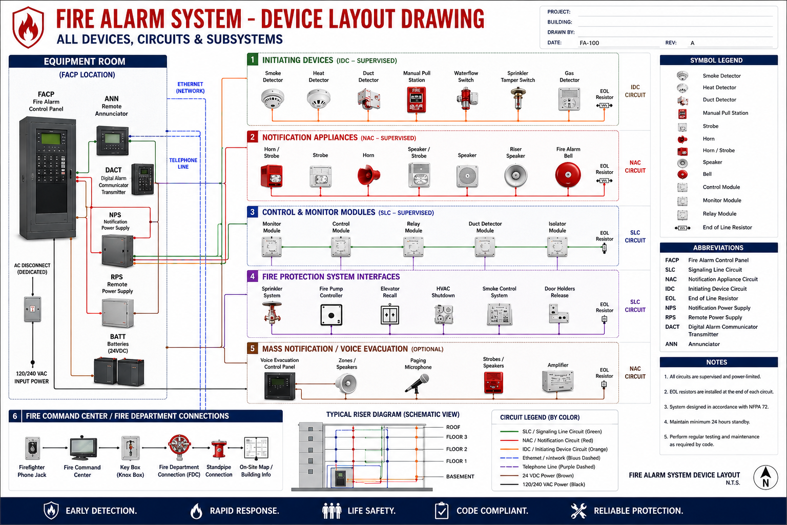
Hover, tap, or focus any component on the drawing (or a circuit below it) for details. Click to pin; move away or click again to clear.
Component Reference
Every component in the drawing above, with its function and the code reference that governs it.
Equipment Room
Fire Alarm Control Panel
The Fire Alarm Control Panel monitors every initiating device, drives the notification appliances, supervises all circuit wiring for opens and ground faults, and reports alarm, supervisory, and trouble conditions. All IDC, NAC, and SLC circuits originate here.
📕 NFPA 72 Ch. 10 & 23Remote Annunciator
A remote annunciator mirrors the panel’s status and provides a code-required display, typically at the building entrance for responding firefighters. It shows zone/point status and may allow acknowledge, silence, and reset functions over a supervised network connection.
📕 NFPA 72 §10.15 / IFCDigital Alarm Communicator (DACT)
The Digital Alarm Communicator Transmitter sends alarm, supervisory, and trouble signals offsite to a supervising (central) station. Traditionally it seizes two telephone lines; modern systems use cellular and IP communicators with supervised paths.
📕 NFPA 72 Ch. 26Notification Power Supply
A notification power supply (NAC power extender) provides additional regulated, supervised, power-limited DC power for notification appliance circuits when panel output is insufficient — common on large strobe/horn loads. It carries its own standby batteries.
📕 NFPA 72 §10.6Remote Power Supply (RPS)
A remote power supply provides additional supervised, power-limited DC power for circuits far from the panel, reducing voltage drop on long notification or auxiliary runs. It carries its own standby batteries.
📕 NFPA 72 §10.6Standby Batteries (24 VDC)
Sealed lead-acid batteries provide the secondary power supply so the system rides through a utility outage — typically 24 hours of standby followed by 5 minutes (or 15 for voice) in alarm. Battery capacity is calculated from the total standby and alarm current draw.
📕 NFPA 72 §10.6.7AC Disconnect (Dedicated)
A dedicated, accessible, clearly marked (typically red, lock-secured) branch-circuit disconnecting means supplies the control panel so primary power cannot be casually removed.
📕 NFPA 72 §10.6 / NEC Art. 760120/240 VAC Input Power
The primary power supply is a dedicated commercial light-and-power branch circuit feeding the panel and power supplies, backed up by the secondary (battery) supply.
📕 NFPA 72 §10.61 — Initiating Devices (IDC)
Smoke Detector
Smoke detectors (photoelectric or ionization) sense visible or invisible products of combustion to provide early warning. Spacing is nominally 30 ft on smooth ceilings, adjusted for ceiling height, beams, and airflow.
📕 NFPA 72 §17.7Heat Detector
Heat detectors respond to a fixed temperature threshold or a rapid rate of temperature rise. They are slower than smoke detectors but suit dirty, dusty, or high-airflow areas where smoke detection would false-alarm.
📕 NFPA 72 §17.6Duct Smoke Detector
A duct smoke detector samples air in HVAC supply/return ductwork through sampling tubes and, on detection, shuts down air-handling units to stop smoke from spreading through the building.
📕 NFPA 72 §17.7.5 / NFPA 90AManual Pull Station
Manual pull stations let occupants initiate an alarm by hand. They are located in the path of egress, within 5 ft of each exit, mounted 42–48 in. above the floor, with travel distance between stations not exceeding 200 ft.
📕 NFPA 72 §17.14Waterflow Switch
A waterflow switch on a sprinkler system detects sustained water movement — indicating an activated sprinkler — and initiates an alarm signal, usually through a retard timer to ignore pressure surges.
📕 NFPA 72 §17.12 / NFPA 13Sprinkler Tamper Switch
A tamper (supervisory) switch monitors the position of a sprinkler control valve and sends a supervisory signal — not an alarm — if the valve is closed, ensuring the sprinkler system is not inadvertently isolated.
📕 NFPA 72 §17.16Gas Detector
A gas detector monitors for combustible or toxic gas (such as CO or methane) and signals the fire alarm or a dedicated panel, providing early warning of hazardous accumulations.
📕 NFPA 72 §17.10 / NFPA 7202 — Notification Appliances (NAC)
Horn / Strobe
A combination horn/strobe provides both audible and visible alarm notification in one appliance. Strobe candela ratings are selected by room size and mounting height; audibility must be 15 dB above ambient.
📕 NFPA 72 Ch. 18Strobe
Strobes provide visible notification for the hearing-impaired and high-noise areas. Candela ratings (15–185 cd) are chosen by room dimensions; synchronization is required where multiple strobes are visible to prevent seizure-inducing flash rates.
📕 NFPA 72 §18.5 / ADAHorn
Horns provide audible notification with a temporal-three (T-3) evacuation pattern. Sound pressure levels must meet audibility above ambient throughout occupiable areas, accounting for door and wall attenuation.
📕 NFPA 72 §18.4Speaker / Strobe
A combination speaker/strobe delivers intelligible voice messages and tones plus a synchronized visible strobe, satisfying both audible and ADA visible notification in one appliance.
📕 NFPA 72 Ch. 18 & 24Speaker
Speakers deliver both alarm tones and intelligible voice messages from a voice evacuation system. They are tapped at a selected wattage to balance coverage and amplifier load, and must meet speech-intelligibility targets.
📕 NFPA 72 Ch. 18 & 24Riser Speaker
A riser (stairwell) speaker is a higher-output speaker used in vertical shafts and large-volume spaces to maintain speech intelligibility for phased evacuation messaging.
📕 NFPA 72 Ch. 24Fire Alarm Bell
Bells are an older audible notification appliance, still used in some facilities and on water-motor gongs for sprinkler waterflow. Newer designs favor horns and speakers for coded and voice signaling.
📕 NFPA 72 Ch. 183 — Control & Monitor Modules (SLC)
Monitor Module
An addressable monitor module reports the state of a conventional dry-contact device (waterflow, tamper, conventional IDC zone) back to the panel as a single addressable point on the signaling line circuit.
📕 NFPA 72 Ch. 23Control Module
An addressable control module provides a supervised output from the SLC — switching a NAC, releasing a door holder, or sending a signal to another system — under the panel’s control-by-event programming.
📕 NFPA 72 Ch. 23Relay Module
A relay module provides Form-C dry contacts driven from the SLC to interface non-supervised auxiliary functions — elevator recall, HVAC shutdown, or signaling third-party equipment.
📕 NFPA 72 Ch. 21 & 23Duct Detector Module
A duct detector module brings a duct smoke detector onto the addressable SLC and provides the relay output that shuts down the associated air-handling unit on detection.
📕 NFPA 72 §17.7.5 / NFPA 90AFault Isolator Module
Isolator modules segment the signaling line circuit so a single wire-to-wire short only disables the devices between two isolators, keeping the rest of the loop operational — essential for Class A / Class X survivability.
📕 NFPA 72 §12.3 (Class X)4 — Fire Protection System Interfaces
Sprinkler System
The fire alarm system monitors the automatic sprinkler system for waterflow (alarm) and valve, pressure, and temperature supervisory conditions, integrating wet-pipe suppression with detection and notification.
📕 NFPA 72 §17.12 / NFPA 13Fire Pump Controller
The fire pump controller’s run, power-loss, and phase-reversal/trouble contacts are monitored by the fire alarm system so pump status is annunciated and transmitted offsite.
📕 NFPA 72 §17.13 / NFPA 20Elevator Recall
Lobby and hoistway/machine-room smoke detectors initiate Phase I emergency recall, returning elevators to a designated level and signaling firefighters, coordinated with shunt-trip where required.
📕 NFPA 72 §21.6 / ASME A17.1HVAC Shutdown
On duct or area smoke detection, the fire alarm system shuts down or repositions air-handling equipment and dampers to limit smoke migration through the building’s ductwork.
📕 NFPA 72 §21.7 / NFPA 90ASmoke Control System
The smoke control interface commands dedicated smoke-management functions — stairwell pressurization, smoke exhaust, and damper control — and monitors their status, often via a firefighters’ smoke control station.
📕 NFPA 72 §21.7 / NFPA 92Door Holder Release
Magnetic door holders keep fire/smoke-barrier doors open for daily use; on alarm the fire alarm system drops power to the magnets so the doors close and maintain the rated barrier.
📕 NFPA 72 §21.9 / NFPA 805 — Mass Notification / Voice Evacuation
Voice Evacuation Control Panel
An emergency voice/alarm communication system (EVACS) delivers prerecorded and live voice instructions for phased or relocation evacuation. It must meet speech-intelligibility requirements across all notification zones.
📕 NFPA 72 Ch. 24Zones / Speakers
Speaker circuits are arranged in notification zones so messages can be directed to specific floors or areas during a phased evacuation, each zone separately amplified and supervised.
📕 NFPA 72 Ch. 24Paging Microphone
The paging microphone at the voice panel lets responders override automatic messages with live voice instructions to selected notification zones during an emergency.
📕 NFPA 72 Ch. 24Strobes / Speakers
Notification appliances driven by the voice evacuation system — combination strobes and speakers — providing audible voice messaging plus ADA-compliant visible signaling.
📕 NFPA 72 Ch. 18 & 24Amplifier
Audio amplifiers provide the power to drive the 25 V/70 V speaker zones with backup amplification and supervised outputs, sized to the total connected speaker wattage plus reserve.
📕 NFPA 72 Ch. 246 — Fire Command Center / FD Connections
Firefighter Phone Jack
Firefighter telephone jacks provide a supervised two-way voice path between remote floors/areas and the fire command center for use by responding firefighters.
📕 NFPA 72 §24.8Fire Command Center
The fire command center is the designated location containing the system annunciator, voice controls, smoke-control station, and documentation for fire-department use during an incident.
📕 IFC §508 / NFPA 72Key Box (Knox Box)
A Knox/key box is a secure, tamper-evident box at the entrance holding building keys and access cards so the fire department can enter without forcing doors.
📕 IFC §506Fire Department Connection (FDC)
The fire department connection lets responders pump supplemental water into the sprinkler or standpipe system; its supervisory devices can be monitored by the fire alarm system.
📕 NFPA 13 / NFPA 14Standpipe Connection
Standpipe hose connections supply water for fire-department hose lines within the building, coordinated with the fire alarm system and FDC.
📕 NFPA 14On-Site Map / Building Info
Site and building information — floor plans, riser diagrams, hazardous-materials data, and device locations — provided at the command center to orient responders.
📕 IFC §508Circuits & Connections
The circuit and communication types that wire the system together.
IDC — Initiating Device Circuit
A conventional, supervised two-wire circuit connecting initiating devices (smoke/heat detectors, pull stations) back to the panel. An end-of-line (EOL) resistor lets the panel supervise wiring integrity — an open reads as a trouble, a short as an alarm (Class B) — so faults cannot go unnoticed.
📕 NFPA 72 §12 & §23NAC — Notification Appliance Circuit
A supervised, power-limited DC circuit that powers notification appliances (horns, strobes, speakers). It is supervised by an EOL resistor, and voltage drop must be calculated so the last appliance still receives voltage within its listed range.
📕 NFPA 72 §12 & §23SLC — Signaling Line Circuit
The addressable communication bus between the panel and addressable devices and modules. It carries data and power and individually supervises every point by address. Class A / Class X loops return to the panel for survivability against a single fault.
📕 NFPA 72 §12 & §23Control Interface
Supervised outputs and dry-contact relays from the panel that command other building systems on alarm — elevator recall, HVAC/damper shutdown, magnetic door-holder release, and fire-pump monitoring — per the system’s control-by-event programming.
📕 NFPA 72 Ch. 21Ethernet / Network Link
A supervised data link between the control panel and peripherals such as remote annunciators or other networked panels, so status and control stay synchronized across the system.
📕 NFPA 72 §10.15Telephone / Communicator Path
The transmission path the DACT uses to report alarm, supervisory, and trouble signals to the supervising (central) station. Legacy installs seize two phone lines; modern systems use supervised IP and cellular paths.
📕 NFPA 72 Ch. 26DC Power Distribution
24 VDC primary power plus a secondary (battery) supply feeding the panel and notification power supplies. Capacity is sized for 24 hours of standby followed by the required alarm period.
📕 NFPA 72 §10.6