Physical Security Engineering System Architecture
From threat assessment to day-two operations — the full 8-step end-to-end physical security system lifecycle (assess & plan, design & engineer, specify & document, procure & stage, install & integrate, test & commission, operate & monitor, and maintain & improve), the five core disciplines that make up the system (access control, video surveillance/CCTV, intrusion detection, low-voltage infrastructure, and integration & interoperability), the layered defense-in-depth model, a typical security network architecture, camera coverage design, threat categories, and the codes and standards that govern it all. Hover, tap, or focus any component for its description and standard reference.
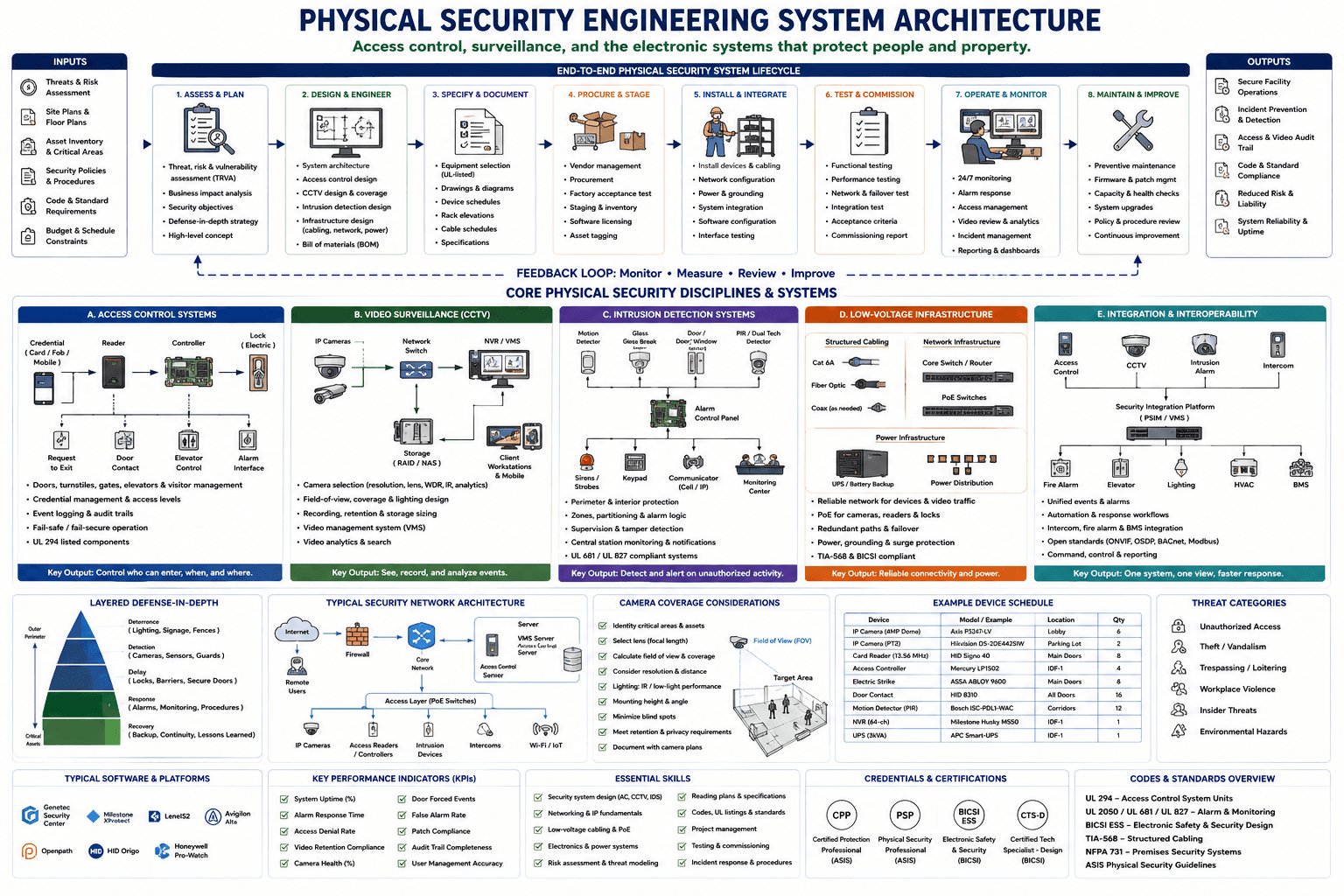
Hover, tap, or focus any component on the drawing (or a circuit below it) for details. Click to pin; move away or click again to clear.
Component Reference
Every component in the diagram above, grouped by section, with its role and the relevant standard.
Inputs
Threats & Risk Assessment
The starting input to the lifecycle: a threat, risk & vulnerability assessment (TRVA) that identifies adversaries, assets, and likely attack scenarios. Everything downstream — layered defenses, camera coverage, access control policy — traces back to this assessment.
📘 ASIS PSC.1 (Risk Assessment)Site Plans & Floor Plans
Architectural floor plans, site plans, and reflected ceiling plans that establish room layouts, sightlines, door locations, and mounting surfaces. Camera field-of-view, reader placement, and cable routing are all derived from these drawings.
📘 AIA Drawing ConventionsAsset Inventory & Critical Areas
A catalog of critical assets, data centers, cash-handling areas, and restricted zones that need the highest layer of protection. Drives which doors get card+PIN vs. card-only, and which spaces get camera coverage with the longest retention.
📘 ASIS PSC.1Security Policies & Procedures
Existing security policies, visitor procedures, and access-level rules that the electronic system must enforce technically — who can badge into which door, when, and under what escort requirements.
📘 ASIS Physical Security GuidelinesCode & Standard Requirements
The applicable codes and standards — UL 294 for access control, NFPA 72/731 for alarm and life safety, IBC egress requirements — that constrain hardware selection and fail-safe/fail-secure decisions from day one.
📘 UL 294 / NFPA 731 / IBCBudget & Schedule Constraints
Capital budget and project schedule constraints that shape the procure/stage phase — vendor selection, lead times on long-lead hardware (mag-locks, servers), and phased rollout planning.
📘 PMI Project ManagementOutputs
Secure Facility Operations
The overall outcome of the lifecycle: day-to-day facility operations that are protected by working access control, video surveillance, and intrusion detection — the reason the whole architecture exists.
Incident Prevention & Detection
Layered defenses (deterrence, detection, delay) and 24/7 monitoring combine to prevent incidents where possible and detect them quickly when prevention fails.
Access & Video Audit Trail
Every badge swipe, door event, and recorded video clip forms a searchable audit trail — essential for incident investigation, compliance audits, and liability defense.
Code & Standard Compliance
A commissioned system that meets UL 294, NFPA 72/731, and local AHJ (Authority Having Jurisdiction) requirements — verified during the test & commission phase and re-verified on every code cycle.
Reduced Risk & Liability
Working physical security controls measurably reduce the organization's exposure to theft, workplace violence, and negligent-security liability claims.
System Reliability & Uptime
Redundant network paths, UPS-backed power, and a disciplined maintain & improve phase keep the security system available — a door that fails locked or a camera that keeps recording matters more than any single feature.
End-to-End Physical Security System Lifecycle
1. Assess & Plan
The first lifecycle phase: threat, risk & vulnerability assessment (TRVA), business impact analysis, and setting security objectives and a defense-in-depth strategy at a high level before any hardware is chosen.
📘 ASIS PSC.12. Design & Engineer
Detailed engineering: system architecture, access-control design, CCTV design & coverage, intrusion-detection design, and the supporting infrastructure design (cabling, network, power) plus the bill of materials.
📘 BICSI ESS Design Guide3. Specify & Document
Turning the design into procurable, buildable documents: UL-listed equipment selection, drawings & diagrams, device schedules, rack elevations, cable schedules, and written specifications.
📘 UL 294 (listed equipment)4. Procure & Stage
Vendor management, procurement, factory acceptance testing (FAT), staging & inventory control, software licensing, and asset tagging before equipment ever reaches site.
5. Install & Integrate
Field installation: mounting and cabling devices, network configuration, power & grounding, system integration between subsystems, software configuration, and interface testing.
📘 TIA-568 / BICSI ESS6. Test & Commission
Functional testing, performance testing, network & failover testing, integration testing against acceptance criteria, and a formal commissioning report before handover to operations.
7. Operate & Monitor
Day-to-day operations: 24/7 monitoring, alarm response, access management, video review & analytics, incident management, and reporting & dashboards for stakeholders.
8. Maintain & Improve
The sustaining phase: preventive maintenance, firmware & patch management, capacity & health checks, system upgrades, policy & procedure review, and continuous improvement.
Feedback Loop: Monitor • Measure • Review • Improve
The dashed feedback loop that closes the lifecycle: data from operating & monitoring (incident trends, false-alarm rates, KPI dashboards) and from maintain & improve flows back into the assess & plan phase, so the system keeps getting better instead of standing still after commissioning.
A. Access Control Systems
Access Control Signal Chain
The core access-control signal chain: a credential (card, fob, or mobile) is presented to a reader, which passes the read to a door controller; the controller makes the access decision and drives the electric lock. Request-to-exit, door contact, elevator control, and alarm interface all report status back to the controller.
📘 UL 294Access Control — Scope & Key Output
Access control covers doors, turnstiles, gates, elevators, and visitor management; credential management and access-level assignment; event logging & audit trails; fail-safe vs. fail-secure hardware selection; and UL 294-listed components throughout. Key output: control who can enter, when, and where.
📘 UL 294B. Video Surveillance (CCTV)
CCTV Signal Chain
IP cameras feed a network switch, which carries video to the NVR/VMS for recording and live viewing. The VMS writes to RAID/NAS storage and serves client workstations and mobile apps for review — the same backbone used for video analytics and search.
📘 ONVIFVideo Surveillance — Scope & Key Output
CCTV design covers camera selection (resolution, lens, WDR, IR, analytics), field-of-view/coverage/lighting design, recording retention & storage sizing, the video management system (VMS), and video analytics & search. Key output: see, record, and analyze events.
📘 ONVIF / H.265C. Intrusion Detection Systems
Intrusion Detection Signal Chain
Motion detectors, glass-break sensors, door/window contacts, and PIR/dual-tech detectors all report to the alarm control panel, which drives sirens/strobes and a keypad, and communicates — over cellular or IP — to a central monitoring center.
📘 UL 681 / UL 827Intrusion Detection — Scope & Key Output
Intrusion detection covers perimeter & interior protection, zones/partitioning & alarm logic, supervision & tamper detection, central-station monitoring & notifications, and UL 681/UL 827-compliant systems. Key output: detect and alert on unauthorized activity.
📘 UL 681 / UL 827D. Low-Voltage Infrastructure
Structured Cabling
The physical media layer: Cat 6A copper for most IP devices, fiber optic for long/high-bandwidth runs (camera risers, building-to-building links), and coax where legacy analog cameras still need it.
📘 TIA-568Network Infrastructure
The core switch/router aggregates traffic from the security network, while PoE switches deliver both data and power to cameras, readers, and locks over a single cable run — simplifying installation and centralizing backup power.
📘 IEEE 802.3bt (PoE++)Power Infrastructure
UPS/battery backup keeps panels, NVRs, and PoE switches running through a utility outage, while power distribution fans that backed-up power out to the devices that need it — sized so life-safety-adjacent devices ride through an outage.
📘 NFPA 70 (NEC)Low-Voltage Infrastructure — Scope & Key Output
Low-voltage infrastructure covers reliable networking for devices & video traffic, PoE for cameras/readers/locks, redundant paths & failover, power/grounding & surge protection, and TIA-568 & BICSI compliance. Key output: reliable connectivity and power.
📘 TIA-568 / BICSIE. Integration & Interoperability
Integrated Subsystems
The four core electronic security subsystems — access control, CCTV, intrusion alarm, and intercom — each feed events and status up into a single integration platform instead of running as isolated silos.
📘 ONVIF / OSDPSecurity Integration Platform (PSIM/VMS)
A Physical Security Information Management (PSIM) or VMS platform correlates events from every subsystem and, in turn, talks to building systems — fire alarm, elevator, lighting, HVAC, and the BMS — for unified, automated response (e.g., unlock egress doors and release elevators on a fire-alarm signal).
📘 OSDP / BACnet / ModbusIntegration — Scope & Key Output
Integration & interoperability covers unified events & alarms, automation & response workflows, intercom/fire-alarm/BMS integration, open standards (ONVIF, OSDP, BACnet, Modbus), and command/control/reporting. Key output: one system, one view, faster response.
📘 ONVIF / OSDP / BACnet / ModbusLayered Defense-in-Depth
Deterrence
The outermost ring of the defense-in-depth pyramid: lighting, signage, and fences that discourage an adversary before they ever attempt to breach the perimeter. Cheapest layer per unit of risk reduction, and the first one CPTED design addresses.
📘 CPTEDDetection
Cameras, intrusion sensors, and guard patrols that notice an intrusion attempt is underway — the layer that turns an unnoticed breach into a detected, response-triggering event.
📘 CPTEDDelay
Locks, barriers, and secure doors engineered to slow an adversary down — buying time between detection and an effective response, which is the entire point of a delay layer.
📘 UL 437 / ASTM F476Response
Alarms, monitoring-center dispatch, and documented response procedures that bring guards, police, or other responders to the scene while the delay layer is still holding.
📘 NFPA 731Recovery
The innermost layer around critical assets: backup, business-continuity planning, and after-action lessons-learned that restore operations and feed improvements back into the next design cycle.
Typical Security Network Architecture
Internet / Cloud
External internet connectivity for cloud VMS, remote monitoring, and vendor support — reached only through the firewall, never with a direct path onto the security network.
📘 IEC 62443 (zones)Remote Users
Remote administrators and integrators who need VPN-authenticated access to the VMS or access-control head-end for support, without being on-site or on the local network.
Firewall
A dedicated firewall that segments the security network from the general IT network and the internet — the single enforced boundary that keeps a compromised office PC from reaching a camera or a door controller.
📘 IEC 62443Core Network
The core switch/router that ties the firewall, the server rack, and the downstream access-layer switches together — the backbone all security traffic transits.
Server Rack (VMS / Access Control / DB)
The head-end server rack: a VMS server recording and managing video, an access-control server making credential decisions, and a database storing events, credentials, and video metadata.
Access Layer (PoE Switches)
The access-layer PoE switches that every field device — cameras, readers, sensors, intercoms, wireless APs — physically connects to, delivering both data uplink and DC power over the same cable.
📘 IEEE 802.3btIP Cameras
IP cameras connect directly to the PoE access layer, streaming video upstream to the NVR/VMS while drawing operating power down the same Cat 6A run.
Access Readers / Controllers
Card/mobile readers and door controllers connect to the access layer over IP (or via OSDP to a local controller), sending credential reads up to the access-control server for the access decision.
📘 OSDPIntrusion Devices
IP-connected alarm panels and sensor concentrators that report zone status up through the access layer to the central monitoring center.
Intercoms
IP intercoms at entries and emergency call points connect to the access layer, carrying two-way audio/video to the monitoring center or reception desk.
Wi-Fi / IoT
Wireless access points and IoT security sensors (environmental, occupancy, wireless locks) extend the access layer to devices that can't take a home-run cable.
Camera Coverage Considerations
Camera Coverage Design Checklist
The camera-coverage design sequence: identify critical areas & assets, select lens focal length, calculate field of view & coverage, consider resolution & distance, plan lighting (IR/low-light performance), set mounting height & angle, minimize blind spots, meet retention & privacy requirements, and document the result with camera plans.
Field of View (FOV) & Target Area
A camera's field of view projects out from the lens as a cone that widens with distance, defining the target area actually captured on the sensor — the geometric basis for every coverage, overlap, and pixel-density calculation.
Example Device Schedule
Example Device Schedule
A representative device schedule for a small commercial building: 6 IP dome cameras in the lobby, 2 PTZ cameras in the parking lot, 8 card readers and electric strikes on main doors, 16 door contacts on all doors, 12 PIR motion detectors in corridors, a 4-port access controller and 64-channel NVR at IDF-1, and a 3kVA UPS backing it all up. This is the kind of device schedule produced in the Specify & Document lifecycle phase.
Threat Categories
Unauthorized Access
Someone entering a space they're not credentialed for — tailgating, propped doors, or a stolen/cloned credential. The primary threat that drives access-control design and UL 294 hardware selection.
📘 UL 294Theft / Vandalism
Loss of equipment, inventory, or cash, and deliberate damage to property — addressed through perimeter deterrence, camera coverage of high-value areas, and rapid alarm response.
Trespassing / Loitering
People present on the property without authorization or legitimate business — mitigated through CPTED principles (natural surveillance, territorial reinforcement) as much as through hardware.
📘 CPTEDWorkplace Violence
Violence or threats of violence involving employees, visitors, or the public on-site — addressed with panic buttons, duress alarms, and documented response/lockdown procedures.
Insider Threats
Risk posed by employees or contractors who already hold legitimate credentials — mitigated with least-privilege access levels, audit-trail review, and anomaly detection on badge usage.
Environmental Hazards
Non-adversarial hazards — fire, flood, severe weather — that the security system must still support through fail-safe egress hardware and integration with fire-alarm and life-safety systems.
📘 NFPA 731Typical Software & Platforms
VMS & Access Control Platforms
Leading enterprise video management and access-control head-end platforms: Genetec Security Center, Milestone XProtect, LenelS2, and Avigilon Alta — the software layer that unifies devices from many hardware vendors under one operator interface.
Access Control & Intercom Platforms
Cloud-managed and enterprise access-control platforms — Openpath (now Avigilon Alta), HID Origo, and Honeywell Pro-Watch — covering the range from mobile-credential cloud systems to traditional on-prem enterprise deployments.
Key Performance Indicators (KPIs)
System Health KPIs
Operational health metrics: system uptime (%), alarm response time, access denial rate, video retention compliance, and camera health (%) — the dashboard a security operations team watches daily.
Security Effectiveness KPIs
Effectiveness and compliance metrics: door forced-open events, false alarm rate, patch compliance, audit trail completeness, and user management accuracy — the metrics that show whether the system is actually being maintained.
Essential Skills
Technical Design Skills
Core technical skills: security system design across AC/CCTV/IDS, networking & IP fundamentals, low-voltage cabling & PoE, electronics & power systems, and risk assessment & threat modeling.
Professional Practice Skills
Professional-practice skills: reading plans & specifications, codes/UL listings & standards knowledge, project management, testing & commissioning, and incident response & procedures.
Credentials & Certifications
CPP — Certified Protection Professional
ASIS International's Certified Protection Professional (CPP) credential — the board-certification standard for security management professionals, covering security principles, business practices, and physical security.
📘 ASIS CPPPSP — Physical Security Professional
ASIS International's Physical Security Professional (PSP) credential, focused specifically on physical security assessment, application, and system design — the most directly relevant ASIS credential for this diagram's scope.
📘 ASIS PSPBICSI ESS — Electronic Safety & Security
BICSI's Electronic Safety & Security (ESS) credential, focused on the design of access control, CCTV, and intrusion-detection systems as part of the broader low-voltage/ICT discipline.
📘 BICSI ESSCTS-D — Certified Technology Specialist, Design
AVIXA/BICSI's Certified Technology Specialist – Design (CTS-D) credential, covering the design of AV and low-voltage integrated systems — relevant to the integration & interoperability layer of a security system.
📘 CTS-DCodes & Standards Overview
UL 294 — Access Control System Units
UL 294, the Standard for Access Control System Units, covers the construction, performance, and testing of access-control equipment — the listing standard the "UL 294-listed components" callouts throughout this diagram refer to.
📘 UL 294UL 2050 / UL 681 / UL 827 — Alarm & Monitoring
UL 2050 (National Industrial Security Systems), UL 681 (Installation and Classification of Burglar and Holdup Alarm Systems), and UL 827 (Central-Station Alarm Services) — the listing standards governing intrusion alarm installation and central-station monitoring referenced in this diagram.
📘 UL 2050 / UL 681 / UL 827BICSI ESS — Electronic Safety & Security Design
BICSI's Electronic Safety & Security (ESS) design reference manual, covering best practices for designing access control, video surveillance, and intrusion-detection systems as low-voltage/ICT infrastructure.
📘 BICSI ESSTIA-568 — Structured Cabling
TIA-568, the Commercial Building Telecommunications Cabling Standard, governs the structured cabling (Cat 6A, fiber) that every camera, reader, and sensor in this diagram ultimately connects through.
📘 TIA-568NFPA 731 — Premises Security Systems
NFPA 731, the Standard for the Installation of Electronic Premises Security Systems, covers installation, testing, and maintenance requirements for the access control, video, and intrusion systems this diagram depicts.
📘 NFPA 731ASIS Physical Security Guidelines
ASIS International's Physical Security guideline series — industry best-practice guidance covering risk assessment, protection-in-depth, and physical security system design that underpins much of this diagram.
Connections & Flows
The signal and data flows that tie the diagram together — each shown as a colored line in the legend above.
Lifecycle Sequence Flow
The solid navy arrows that carry the project through the 8-step end-to-end physical security system lifecycle, in order, from Assess & Plan through Maintain & Improve.
Feedback Loop
The dashed loop beneath the 8-step lifecycle: operating data, KPIs, and lessons learned flow back from Operate & Monitor and Maintain & Improve into Assess & Plan, closing the loop instead of ending at commissioning.
Device Signal Chain
The solid black/gray arrows within the Access Control, CCTV, and Intrusion Detection panels — the field-device-to-panel signal path (reader to controller to lock; camera to switch to NVR; sensor to alarm panel) that each subsystem is built from.
Network / Data Flow
The blue arrows in the Typical Security Network Architecture and Integration diagrams — IP data flow from the internet through the firewall and core network to the server rack and access-layer switches, and from the integration platform out to building systems.