Aerospace Engineering System Architecture
From concept to flight and beyond — the full aerospace vehicle lifecycle, organized around the project stages (requirements through disposal), the vehicle categories and flight environments they operate in, and the 8 core engineering disciplines (aerodynamics, propulsion, structures, flight mechanics, stability & control, orbital mechanics, aerospace structures, and avionics) that design them. Hover, tap, or focus any component or connection for its description and standard reference.
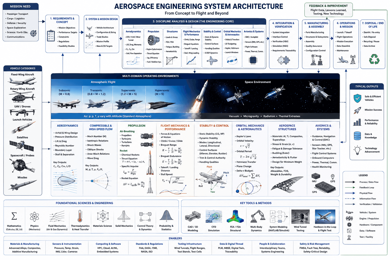
Hover, tap, or focus any component on the drawing (or a circuit below it) for details. Click to pin; move away or click again to clear.
Component Reference
Every component in the diagram above, grouped by section, with its role and the relevant standard.
Project Lifecycle
Mission Need
The originating demand that justifies a new aerospace program — passenger transport, cargo/logistics, defense/security, space exploration, science/Earth observation, or communications. Every downstream requirement traces back to one of these mission classes.
📘 NASA Systems Engineering Handbook (NPR 7123.1)1. Requirements & Concept
Translates the mission need into mission objectives, performance targets, constraints, and applicable regulations, then validates it all with feasibility studies before committing engineering resources to a concept.
📘 ARP4754A (Certification Considerations)2. System & Mission Design
Defines the vehicle architecture, configuration, and sizing; runs trade studies across competing concepts; and sets the mission profile plus mass and center-of-gravity targets that every discipline downstream must design to.
📘 NASA SE Handbook (Concept Studies)3. Discipline Analysis & Design (The Engineering Core)
The engineering core where aerodynamics, propulsion, structures, flight mechanics, stability & control, orbital mechanics, aerospace structures, and avionics each perform detailed analysis and design against the mission profile — detailed further in the discipline band below.
📘 AIAA S-Series Standards4. Integration & Verification
Integrates the disciplines' outputs into a coherent system, resolves interface conflicts, and runs verification & validation — modeling & simulation plus requirements traceability — to confirm the design actually meets its requirements before committing to manufacturing.
📘 ARP4754A / DO-178C (Verification)5. Manufacturing & Assembly
Manufactures parts and subsystems, assembles the vehicle, and runs quality assurance and configuration control to ensure the as-built vehicle matches the certified design.
📘 AS9100 (Aerospace QMS)6. Operations & Mission
Executes the vehicle's operational mission — launch/takeoff, flight operations, mission execution, data downlink, and ongoing maintenance — the phase every prior stage was designed to enable.
📘 NASA SE Handbook (Operations)7. Disposal / End of Life
Retires the vehicle responsibly at end of life — deorbit/re-entry for spacecraft, safe disposal, recycling/reuse of materials, and archiving mission data for future reference.
📘 NASA-STD-8719.14 (Orbital Debris)Feedback & Improvement
Flight data, lessons learned, and testing results feed back into new technology development and future requirements — the loop that lets each aerospace program improve on the last rather than starting from zero.
📘 NASA SE Handbook (Continuous Improvement)Vehicle Categories
Fixed-Wing Aircraft
Aircraft that generate lift from a fixed airfoil moving through the air — the broadest vehicle category, spanning general aviation through commercial airliners and military fighters.
📘 14 CFR Part 25 (Transport Category)Rotary-Wing Aircraft
Helicopters and other rotorcraft generate lift from rotating airfoils (rotor blades) rather than fixed wings, trading cruise efficiency for vertical takeoff/landing and hover capability.
📘 14 CFR Part 27 / Part 29UAV / Drones
Uncrewed Aerial Vehicles ranging from small multirotor drones to large fixed-wing military and surveillance platforms — the fastest-growing vehicle category, with its own airspace-integration and autonomy challenges.
📘 14 CFR Part 107 (Small UAS)Launch Vehicles
Multi-stage rockets designed to accelerate a payload from the ground to orbital (or escape) velocity — the domain where rocket propulsion and structural mass fraction dominate every design decision.
📘 NASA-STD-5012 (Launch Vehicle Structures)Satellites
Spacecraft placed into a stable orbit to perform communications, navigation, Earth observation, or science missions — governed by orbital mechanics rather than aerodynamics once on-station.
📘 CCSDS Standards (Satellite Ops)Spacecraft / Probes
Crewed spacecraft and deep-space probes designed for transit, rendezvous, or exploration beyond a single stable orbit — adding thermal, radiation, and life-support (if crewed) constraints on top of orbital mechanics.
📘 NASA-STD-3001 (Human Spaceflight)Missiles
Guided munitions combining rocket or air-breathing propulsion with a guidance, navigation, and control system to reach a designated target — a vehicle category where aerodynamics, propulsion, and avionics are especially tightly coupled.
📘 MIL-STD-1521 (Technical Reviews)Multi-Domain Operating Environments
Subsonic Flight (M < 0.8)
Flight below Mach 0.8, where compressibility effects are small and classical incompressible aerodynamics (thin-airfoil theory, simple lift/drag relations) predicts vehicle behavior well. Covers the vast majority of general aviation and commercial airliner cruise.
📘 ICAO Standard AtmosphereTransonic Flight (0.8 < M < 1.2)
The regime spanning Mach 0.8–1.2, where flow over parts of the vehicle is locally supersonic while the freestream is still subsonic — the domain of the transonic drag rise and the area rule for minimizing wave drag.
📘 NACA Area Rule (Whitcomb)Supersonic Flight (1.2 < M < 5)
Flight from Mach 1.2 to 5, dominated by oblique and bow shock waves, wave drag, and supersonic wing planform design — the domain of fighter aircraft and supersonic transports.
📘 NASA SP-8006 (Supersonic Aero)Hypersonic Flight (M > 5)
Flight above Mach 5, where aerothermodynamic heating becomes a primary design driver alongside aerodynamics — thermal protection systems, real-gas effects, and shock-layer chemistry dominate vehicle design at these speeds.
📘 NASA-STD-6016 (Hypersonic TPS)Space Environment
Beyond the sensible atmosphere, vehicles operate in vacuum with microgravity, ionizing radiation, and extreme thermal cycling — an environment governed entirely by orbital mechanics and thermal/radiation design rather than aerodynamics.
📘 NASA-STD-3001 / ECSS-E-ST-10Typical Outputs
Safe & Efficient Vehicles
The end product of the whole architecture — vehicles that meet certification safety requirements while achieving the performance and efficiency targets set in the requirements phase.
📘 14 CFR Part 25 (Airworthiness)Mission Success
The vehicle successfully accomplishes the mission that justified the program in the first place — the ultimate measure of whether the requirements-to-operations pipeline actually worked.
📘 NASA SE Handbook (Mission Success Criteria)Performance & Reliability
The vehicle sustains its designed performance envelope and reliability targets across its operational lifetime — validated through the fatigue, reliability, and durability analysis performed in the structures and integration phases.
📘 MIL-STD-785 (Reliability Program)Data & Knowledge
Flight test and operational data generate engineering knowledge that improves models, validates assumptions, and de-risks the next program — a direct input to the feedback loop.
📘 NASA SE Handbook (Lessons Learned)Technology Advancement
New materials, propulsion concepts, and analysis methods developed or matured during a program become available technology for the next generation of vehicles.
📘 NASA Technology Readiness Levels (TRL)Discipline Analysis & Design
Aerodynamics
Analyzes airfoil and wing design, pressure distribution, lift and drag, Reynolds number effects, boundary-layer behavior, and stall/separation. Key outputs are the lift, drag, and moment coefficients (Cₗ, C_D, Cₘ) and lift-to-drag ratio (L/D) that every other discipline builds on.
📘 NACA/NASA Airfoil DataCompressible & High-Speed Flow
Governs flow behavior once Mach number effects can no longer be ignored — isentropic relations, shock waves (normal, oblique, and area-Mach relations), and wave drag. Key outputs are Mach number and the flow properties (M, ρ, T, ρ₀/ρ, P₀/P) at each point in the flow.
📘 NACA Report 1135 (Compressible Flow Tables)Propulsion
Covers both air-breathing propulsion (propellers, turbojets, turbofans, ramjets — engine cycle analysis, thrust equation, specific impulse) and rocket propulsion (chemical rockets, the rocket equation, Δv budgeting) that determine how much thrust a vehicle can generate and for how long.
📘 AIAA Aerospace Design Engineers GuideFlight Mechanics & Performance
Applies the forces and equations of motion to real flight profiles — climb, cruise, and glide performance, the Breguet range and endurance equations, takeoff/landing distance, and stall speed — translating raw aerodynamic and propulsion data into mission-level performance.
📘 Breguet Range Equation (Classical)Stability & Control
Analyzes static stability (center of gravity vs. neutral point), dynamic stability modes (longitudinal, lateral, directional), control-surface sizing (aileron, elevator, rudder), trim and control authority, and overall handling qualities — the discipline that keeps a vehicle controllable across its flight envelope.
📘 MIL-STD-1797A (Flying Qualities)Orbital Mechanics & Astronautics
Applies Kepler's laws and orbital velocity/period equations to design orbits and transfers — Hohmann transfers, plane changes, and Δv budgeting (ΔV_total = ΣΔVᵢ) that determine how much propellant a mission requires.
📘 Kepler's Laws / Vis-Viva EquationAerospace Structures
Selects materials (aluminum, titanium, composites, superalloys), analyzes stress and strain, fatigue and damage tolerance, buckling (Euler), aeroelasticity and flutter, and designs for minimum weight — producing the allowables, factor-of-safety, and weight/durability outputs every other discipline depends on for structural margin.
📘 NASA-STD-5001 / MMPDS HandbookAvionics & Systems
Designs guidance, navigation & control (GNC) and autopilot systems, selects sensors (IMU, GPS, star trackers), and builds the flight control software, onboard computers, and power/thermal/communications subsystems that make the vehicle autonomous and controllable.
📘 DO-178C (Airborne Software) / DO-254Foundational Sciences & Engineering
Mathematics (Calculus, DE, LA)
The mathematical foundation underlying every discipline above — calculus for continuous system behavior, differential equations for dynamics, and linear algebra for the state-space and finite-element formulations used throughout aerospace analysis.
📘 ABET Math RequirementsPhysics (Mechanics)
Classical mechanics — Newton's laws, energy and momentum conservation, and rigid-body dynamics — is the physical foundation for flight mechanics, orbital mechanics, and structural analysis alike.
📘 ABET Physics RequirementsFluid Mechanics (Air & Gas Dynamics)
The governing physics of air and gas flow — continuity, momentum, and energy equations — that underlie every aerodynamics and propulsion analysis in the discipline band above.
📘 Navier-Stokes EquationsThermodynamics & Heat Transfer
Thermodynamic cycles and heat-transfer analysis underpin propulsion engine cycle analysis, aerothermodynamic heating in hypersonic flight, and thermal protection system design.
📘 ABET Thermodynamics RequirementsMaterials Science
Understanding material behavior at the microstructural level — alloys, composites, ceramics — informs the material-selection decisions made in the Aerospace Structures discipline above.
📘 MMPDS Handbook (Material Allowables)Solid Mechanics
The theory of stress, strain, and deformation in solid bodies that structural engineers apply to size every load-bearing member in the vehicle.
📘 ABET Solid Mechanics RequirementsControl Theory & Dynamics
Feedback control theory and system dynamics form the mathematical basis for the Stability & Control and Avionics & Systems disciplines — autopilots, GNC, and flight control laws are all applied control theory.
📘 Classical & Modern Control TheoryProbability & Statistics
Probability and statistics underpin reliability engineering, fatigue life prediction, and uncertainty quantification across every discipline — critical for setting factors of safety and reliability targets.
📘 MIL-STD-785 (Reliability Statistics)Key Tools & Methods
CAD / 3D Modeling
Computer-Aided Design tools define the vehicle's geometry in 3D, forming the single source of truth that feeds CFD, FEA, and manufacturing downstream.
📘 ASME Y14.5 (GD&T)CFD Simulation
Computational Fluid Dynamics numerically solves the flow field around a vehicle, complementing (and often reducing the need for) wind-tunnel testing across the aerodynamics and propulsion disciplines.
📘 AIAA CFD Verification & Validation GuideFEA / FEA Structural
Finite Element Analysis numerically predicts stress, deflection, and modal behavior of the vehicle structure, the primary computational tool of the Aerospace Structures discipline.
📘 NASA-STD-5002 (FEM Standards)Multi-Body Dynamics
Simulates the coupled motion of interconnected rigid and flexible bodies — landing gear, deployable mechanisms, control surfaces — used across flight mechanics and structures analysis.
📘 AIAA Multibody Dynamics StandardsSystem Modeling (MATLAB/Simulink)
Block-diagram system modeling tools (MATLAB/Simulink and equivalents) simulate control laws, dynamic response, and system-level behavior — central to the Stability & Control and Avionics & Systems disciplines.
📘 DO-178C (Model-Based Design)Wind Tunnel Testing
Physical scale-model testing in a wind tunnel validates CFD predictions and characterizes aerodynamic behavior — still the gold-standard verification method for aerodynamics and stability & control.
📘 AIAA Wind Tunnel Testing StandardsHardware-in-the-Loop & Flight Test
Hardware-in-the-Loop testing exercises real flight hardware against a simulated environment before committing to flight test — the final, highest-fidelity verification step before a vehicle enters operations.
📘 RTCA DO-160 (Environmental Test)Enablers
Materials & Manufacturing
Advanced alloys, composites, and additive manufacturing capability determine what structural and propulsion designs are actually producible — a hard constraint on the Aerospace Structures and Propulsion disciplines.
📘 AS9100 (Aerospace Manufacturing QMS)Sensors & Instrumentation
Pressure, temperature, and strain sensors plus IMUs, lidar, and cameras provide the measurement data that feeds both ground testing (wind tunnel, structural test) and onboard avionics.
📘 ARINC 429 / 664 (Avionics Data Bus)Computing & Software
High-performance and cloud computing enable large-scale CFD/FEA runs and AI/ML-assisted design exploration, while embedded systems software runs the vehicle's real-time avionics.
📘 DO-178C (Airborne Software Assurance)Standards & Regulations
FAA, EASA, ITAR, NASA, and ISO standards define the regulatory envelope every aerospace program must design and certify within — from airworthiness to export control.
📘 14 CFR / EASA CS-25 / ITAR (22 CFR 120-130)Testing Infrastructure
Physical test infrastructure — wind tunnels, flight test ranges, and propulsion test stands/cells — provides the real-world verification environment the Key Tools & Methods discipline relies on.
📘 AIAA Ground Test Facility StandardsData & Digital Thread
Product Lifecycle Management, Model-Based Systems Engineering, and digital twins maintain a continuous, traceable data thread from requirements through operations — the connective tissue linking every lifecycle stage.
📘 INCOSE MBSE / ISO 10303 (STEP)People & Collaboration
Interdisciplinary engineering teams and systems-engineering process are what actually integrate the 8 discipline outputs into one coherent vehicle — the human enabler behind every technical box in this diagram.
📘 INCOSE Systems Engineering HandbookSafety & Risk Management
Failure Mode and Effects Analysis, fault-tree analysis, reliability engineering, and safety-critical design process identify and mitigate risk across every discipline before it reaches flight.
📘 MIL-STD-882 (System Safety)Connections & Flows
The process, feedback, and information flow types that tie the diagram together — each shown as a colored line in the legend above.
Process / Data Flow
The primary forward flow of the vehicle-development process — from mission need through requirements, discipline design, integration, manufacturing, and operations.
📘 NASA SE Handbook (Process Flow)Feedback Loop
Flight data, lessons learned, and testing results flowing back from operations into future requirements and technology development.
📘 NASA SE Handbook (Continuous Improvement)Physical Flow
The physical movement of hardware, materials, and vehicle articles through the development and production pipeline.
📘 AS9100 (Manufacturing Flow)Information Flow
Non-physical data exchange between disciplines and lifecycle stages — requirements, analysis results, and design data passed digitally.
📘 INCOSE MBSEVerification / Validation
The dedicated V&V flow confirming that each stage's outputs actually satisfy the requirements handed down from the stage before it.
📘 ARP4754A (Verification)