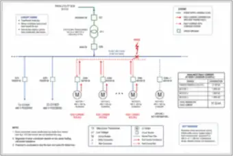
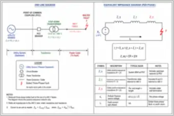
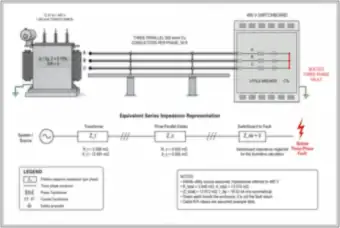
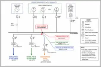
Engineering Illustrations & Drawings

318 labeled drawings across 40 subjects. Each thumbnail opens the full-size drawing with the All-Access pass.

Electrical Power & Calculations

221 drawings

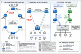
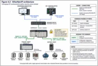
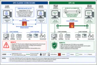
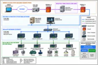
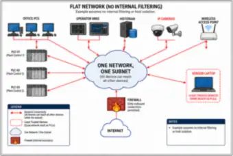
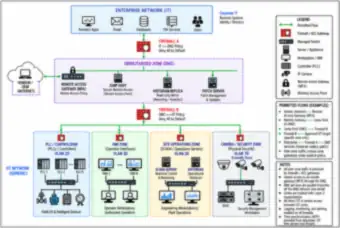
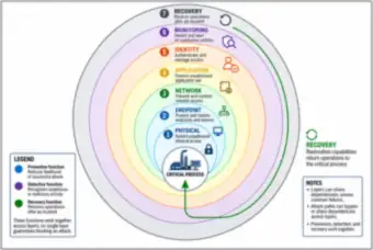
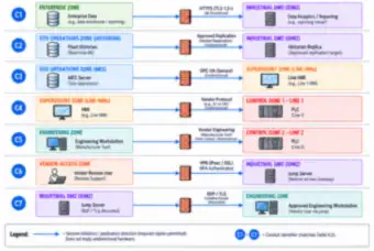
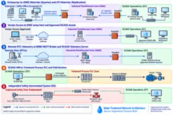
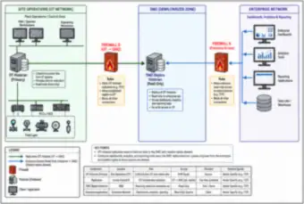
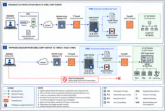
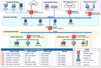
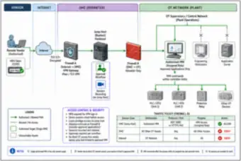
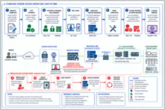
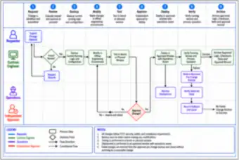
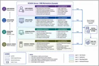
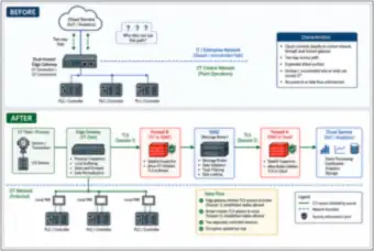
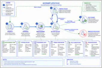
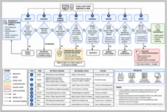
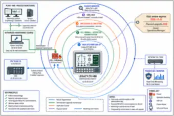
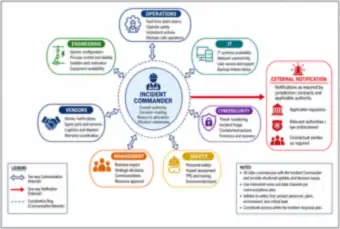
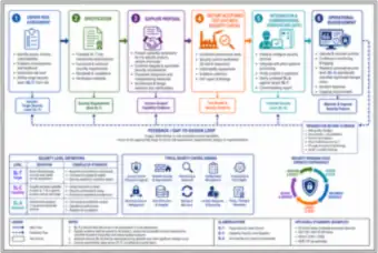
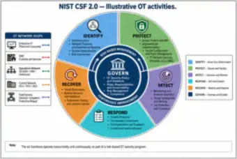
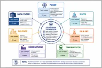
Industrial Control & OT Cybersecurity

82 drawings

Fire Alarm Systems & Inspection

15 drawings

Symbols, Units & Reference

Single-line symbol sheets, electrical quantities, and the Ohm’s law and power formulas
14 drawings
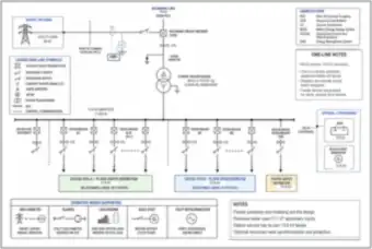
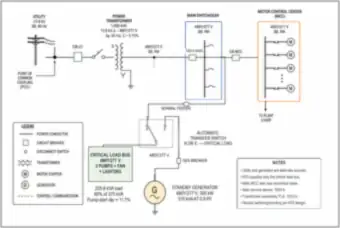
Single-Line Diagram Symbols Reference Sheet (thumbnail)🔒 All-Access

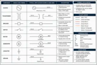
Single-Line Diagram Symbols Reference Sheet

A reference sheet of the common single-line diagram symbols (source, transformer, breaker, switch, motor, generator, capacitor and ground). Each symbol is shown with a typical one-line application and a short description, next to a color legend, abbreviations and usage notes.

Electrical Quantities Reference Chart (thumbnail)🔒 All-Access

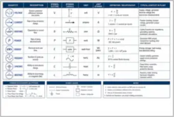
Electrical Quantities Reference Chart

A chart of voltage, current, resistance, power, energy, frequency, capacitance and inductance, giving each quantity its letter and usual symbol, unit, defining relationship and typical context in a plant, with the common AC relationships listed underneath.

Motor Nameplate and Power Unit Conversion Ladder (thumbnail)🔒 All-Access

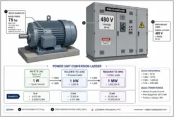
Motor Nameplate and Power Unit Conversion Ladder

A 75 hp, 480 V, three-phase motor nameplate beside a 480 V switchboard label, with a watts, kilowatts and megawatts conversion ladder and worked examples for 75 W, 75 kW and 75 MW.

Ohm's Law and Power Formula Wheel (thumbnail)🔒 All-Access

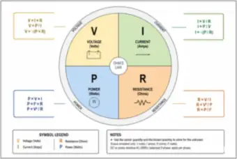
Ohm's Law and Power Formula Wheel

A circular wheel for Ohm's law and the power equations, giving each of voltage, current, resistance and power in terms of the other quantities (for example V = I × R, I = V ÷ R, P = V × I, R = V² ÷ P), with a symbol legend and notes on units.

Symbol Sheet: Sources (Utility, AC, DC, Battery Cell and Battery Bank) (thumbnail)🔒 All-Access

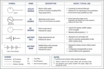
Symbol Sheet: Sources (Utility, AC, DC, Battery Cell and Battery Bank)

A symbol sheet for sources showing the utility source, AC source, DC source, battery cell and battery bank, each with a description and notes on its typical use, plus a legend and notes on polarity.

Symbol Sheet: Transformers, Connections and Instrument Transformers (thumbnail)🔒 All-Access

Symbol Sheet: Transformers, Connections and Instrument Transformers

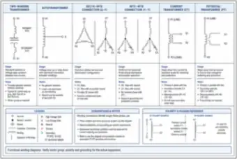
A symbol sheet for the two-winding transformer, autotransformer, delta-wye and wye-wye connections, current transformer and potential transformer, each with usage and notes, and a polarity and phasing reference for CTs and PTs.

Symbol Sheet: Circuit Breakers (MCCB, Power, Air, Vacuum, Fused and Draw-Out) (thumbnail)🔒 All-Access

Symbol Sheet: Circuit Breakers (MCCB, Power, Air, Vacuum, Fused and Draw-Out)

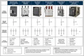
A symbol sheet comparing six breaker types, with a photo, one-line symbol, three-pole elevation and typical application for molded-case, power, air, vacuum, fused and draw-out circuit breakers.

Symbol Sheet: Switches (Disconnect, Fused, Load-Break, Transfer and Bypass-Isolation) (thumbnail)🔒 All-Access

Symbol Sheet: Switches (Disconnect, Fused, Load-Break, Transfer and Bypass-Isolation)

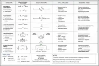
A symbol sheet for five switch types, with each graphic symbol, a single-line example, typical applications and notes, plus device numbers (89 line switch, 43 transfer selector) and a legend.

Symbol Sheet: Motors, Drives, Soft Starters, Starters and Contactors (thumbnail)🔒 All-Access

Symbol Sheet: Motors, Drives, Soft Starters, Starters and Contactors

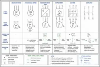
A symbol sheet for induction and synchronous motors, a motor with VFD, a soft starter, a magnetic starter and a contactor, with their power and control symbols, typical connections and descriptions, and notes tied to NEC Article 430.

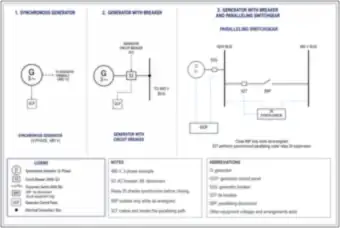
Symbol Sheet: Generators, Generator Breaker and Paralleling Switchgear (thumbnail)🔒 All-Access

Symbol Sheet: Generators, Generator Breaker and Paralleling Switchgear

A symbol sheet for a synchronous generator alone, with a generator circuit breaker (52), and with paralleling switchgear (tie breaker 52T, disconnect 89P and a relay 25 synch-check), with legend, notes and abbreviations.

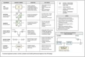
Symbol Sheet: UPS, Rectifier, Inverter, Static Switch, Battery String and Charger (thumbnail)🔒 All-Access

Symbol Sheet: UPS, Rectifier, Inverter, Static Switch, Battery String and Charger

A symbol sheet for UPS and battery equipment giving the graphic symbol, function and key notes for each item, with a typical single-line UPS architecture and a legend for control and monitoring connections.

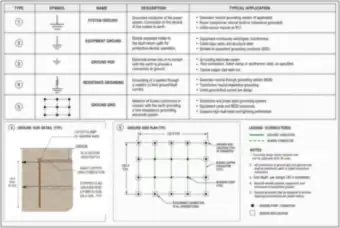
Symbol Sheet: System Ground, Equipment Ground, Ground Rod, Resistance Grounding and Ground Grid (thumbnail)🔒 All-Access
Symbol Sheet: System Ground, Equipment Ground, Ground Rod, Resistance Grounding and Ground Grid
A symbol sheet for five grounding types with their descriptions and typical applications, a ground rod detail (8 ft, 5/8 in. copper-clad) and a 120 ft ground grid plan at a 30 in. design depth.

Symbol Sheet: Ammeter, Voltmeter, Wattmeter, Power Meter and Revenue Meter (thumbnail)🔒 All-Access

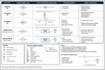
Symbol Sheet: Ammeter, Voltmeter, Wattmeter, Power Meter and Revenue Meter

A symbol sheet for metering showing each meter’s single-line symbol, typical connection, measured quantity and notes, with abbreviations and a CT and VT metering detail.

Symbol Sheet: Overcurrent, Differential, Ground-Fault and Arc-Flash Relays, Surge Arresters and Fuses (thumbnail)🔒 All-Access

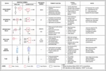
Symbol Sheet: Overcurrent, Differential, Ground-Fault and Arc-Flash Relays, Surge Arresters and Fuses

A symbol sheet for protection devices with their single-line and schematic symbols, ANSI device numbers (50/51, 87, 50N/51N), primary function, typical location and notes, following IEEE C37.2 conventions.

Circuit Fundamentals

DC networks, Kirchhoff’s laws, dividers, sine waves, phasors, resonance and the power triangle
8 drawings
60 Hz Sine Wave: Peak, RMS and Average Values (thumbnail)🔒 All-Access

60 Hz Sine Wave: Peak, RMS and Average Values

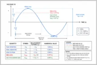
One cycle of a 60 Hz sine wave marked with the peak, peak-to-peak, RMS (0.707 Vp) and half-cycle average (0.637 Vp) levels, the 16.67 ms period and 8.33 ms half-cycle, and a table relating each quantity to the peak value.

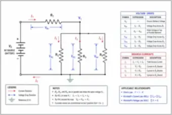
Series-Parallel DC Circuit: Voltage Drops and Branch Currents (thumbnail)🔒 All-Access

Series-Parallel DC Circuit: Voltage Drops and Branch Currents

A DC source feeding R1 in series with three parallel resistors, with the voltage drop across each resistor, the branch currents and the node voltage written out, plus Ohm’s law, Kirchhoff’s current law and Kirchhoff’s voltage law.

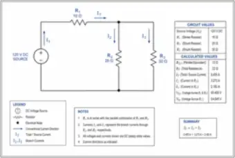
Worked Series-Parallel DC Circuit: 120 V Source (thumbnail)🔒 All-Access

Worked Series-Parallel DC Circuit: 120 V Source

A 120 V DC source with a 10 Ω series resistor feeding 20 Ω and 30 Ω parallel resistors, solved step by step: 12 Ω parallel equivalent, 22 Ω total, 5.455 A source current, 3.273 A and 2.182 A branch currents, and the voltage across each part.

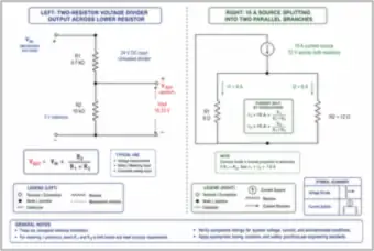
Voltage Divider and Current Divider (thumbnail)🔒 All-Access

Voltage Divider and Current Divider

Two side-by-side examples: a 24 V unloaded voltage divider with 4.7 kΩ and 10 kΩ resistors giving 16.33 V, and a 15 A source splitting into 9 A and 6 A through 8 Ω and 12 Ω parallel branches, with the divider formulas.

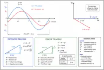
Current Lagging Voltage: Waveforms, Phasors and Triangles (thumbnail)🔒 All-Access

Current Lagging Voltage: Waveforms, Phasors and Triangles

Voltage and current sine waves with current lagging by 30°, the matching phasor diagram, and the impedance triangle and power triangle with their formulas, power factor and the sign convention for reactive power.

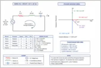
Series RLC Circuit and Phasor Diagram at 120 V, 60 Hz (thumbnail)🔒 All-Access

Series RLC Circuit and Phasor Diagram at 120 V, 60 Hz

A 120 V, 60 Hz series circuit with a 12 Ω resistor, 40 mH inductor and 100 µF capacitor, with the derived reactances, a 16.58 Ω impedance, a 7.24 A current, a 0.724 leading power factor and an RMS phasor diagram.

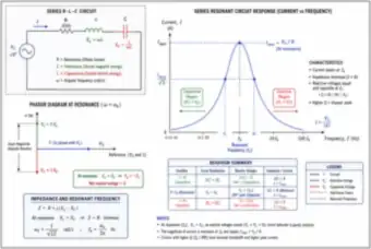
Series Resonant Circuit: Response Curve and Phasors at Resonance (thumbnail)🔒 All-Access

Series Resonant Circuit: Response Curve and Phasors at Resonance

A series R-L-C circuit with its current-versus-frequency resonance curve and half-power points, the phasors at resonance, the impedance and resonant-frequency formulas, and a table of capacitive, resonant and inductive behavior.

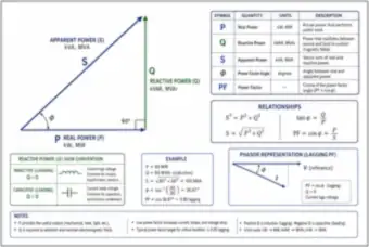
Power Triangle: Real, Reactive and Apparent Power (thumbnail)🔒 All-Access

Power Triangle: Real, Reactive and Apparent Power

The power triangle relating real power P, reactive power Q and apparent power S, with the formulas, a worked example (80 MW and 60 MVAr give 100 MVA at 0.80 power factor), the sign convention for Q and a lagging phasor view.

Single- & Three-Phase Systems

Center-tapped 120/240 V service, wye and delta connections, and balanced and unbalanced loads
9 drawings
120/240 V Single-Phase Service from a Center-Tapped Transformer (thumbnail)🔒 All-Access

120/240 V Single-Phase Service from a Center-Tapped Transformer

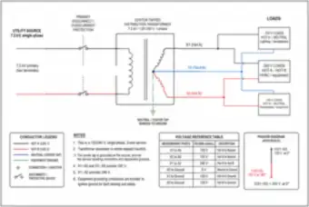
A 7.2 kV single-phase utility source feeding a center-tapped 120/240 V transformer, with the hot, neutral and ground conductors, 120 V and 240 V loads, a voltage reference table and the phasor relationship between the two legs.

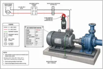
Single-Phase 240 V Motor-Driven Pump with Clamp Ammeter (thumbnail)🔒 All-Access

Single-Phase 240 V Motor-Driven Pump with Clamp Ammeter

A 240 V single-phase supply with a disconnect and fuses feeding a 7.5 kW motor-driven pump. A clamp ammeter on one conductor reads 34.7 A, matching the nameplate calculation of 7,500 W ÷ (240 V × 0.90).

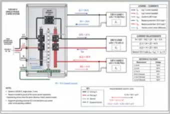
120/240 V Panel: Leg Currents and Neutral Current (thumbnail)🔒 All-Access

120/240 V Panel: Leg Currents and Neutral Current

A single-phase three-wire panel feeding two 120 V loads and one 240 V load, with leg currents of 44 A and 34 A and a 10 A neutral current found from the difference between the two 120 V branches.

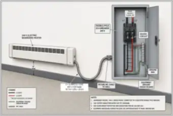
240 V Baseboard Heater Circuit: Breaker, MC Cable and Grounding (thumbnail)🔒 All-Access

240 V Baseboard Heater Circuit: Breaker, MC Cable and Grounding

A 4 kW, 240 V electric baseboard heater on a dedicated 25 A double-pole breaker, wired with 2 × 10 AWG copper plus ground in MC cable. The current is 16.7 A, or 20.8 A at 125%, with a 6 in. minimum clearance and installation notes.

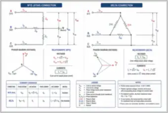
Wye and Delta Three-Phase Connections Compared (thumbnail)🔒 All-Access

Wye and Delta Three-Phase Connections Compared

Side-by-side wye and delta connections with their voltage phasor diagrams, the line and phase voltage and current relationships (√3 factors), and a summary table covering phase and line quantities and neutral availability.

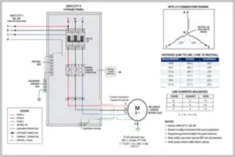
480Y/277 V Three-Phase Panel Feeding a Balanced Motor Load (thumbnail)🔒 All-Access

480Y/277 V Three-Phase Panel Feeding a Balanced Motor Load

A 480Y/277 V, four-wire panel with a three-pole breaker and motor circuit protector feeding a balanced 75 kW motor at 0.88 power factor. The line current works out to 102.5 A, with the wye voltages, neutral bus and equipment ground bus shown.

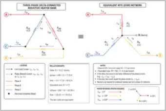
Delta Resistive Heater Bank and Its Equivalent Wye (thumbnail)🔒 All-Access

Delta Resistive Heater Bank and Its Equivalent Wye

A delta-connected bank of three 12 Ω resistors on a 208 V supply, drawing 17.33 A per branch and 30.02 A per line, shown equal to a wye network of three 4 Ω resistors with the same line current.

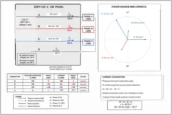
208Y/120 V Four-Wire Panel with Unequal Phase Loads (thumbnail)🔒 All-Access

208Y/120 V Four-Wire Panel with Unequal Phase Loads

A 208Y/120 V panel with phase currents of 120 A, 80 A and 150 A, and the resulting 60.8 A neutral current found as the phasor sum, shown with a phasor diagram, a conductor table and the current convention.

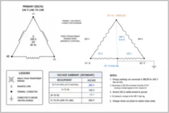
Delta Transformer Bank with Center Tap and High Leg (thumbnail)🔒 All-Access

Delta Transformer Bank with Center Tap and High Leg

A 240 V delta primary and a delta secondary with a center-tapped winding, giving 120 V and 240 V and a 208 V high leg (phase B) to neutral, with a voltage summary table and notes.

Load Calculations, Demand & Energy

Service and equipment loads, demand and load factor, energy use, billing and metering
18 drawings
Battery Capacity and Energy: 12 V, 5 A for 2 Hours (thumbnail)🔒 All-Access

Battery Capacity and Energy: 12 V, 5 A for 2 Hours

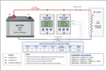
A 12 V battery supplying a 5 A DC load for 2 hours, with a coulomb counter and a watt-hour meter reading 10 Ah (36,000 C) and 120 Wh (0.120 kWh), a series shunt for current sensing, and the capacity, charge and energy relationships.

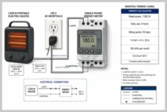
Portable Heater: Monthly Energy Use and Metering (thumbnail)🔒 All-Access

Portable Heater: Monthly Energy Use and Metering

A 1,500 W portable heater on a 120 V receptacle wired through a single-phase energy meter. Four hours a day for 30 days gives 180 kWh per month, and the heater draws 12.5 A at 120 V, shown with the connection diagram and notes.

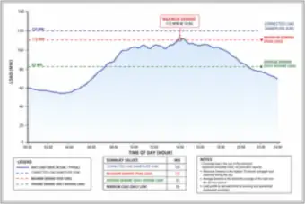
Daily Load Curve: Connected, Maximum and Average Demand (thumbnail)🔒 All-Access

Daily Load Curve: Connected, Maximum and Average Demand

A 24-hour load curve for a facility with 120 MW connected load, a 112 MW maximum demand at 14:00, an 83 MW average demand and a 55 MW daily minimum, with definitions of each term.

Monthly Facility Load Profile and Load Factor (thumbnail)🔒 All-Access

Monthly Facility Load Profile and Load Factor

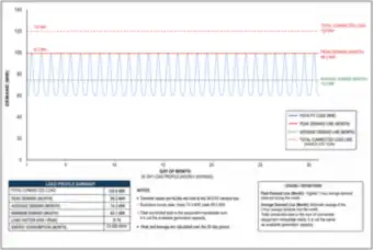
A 30-day hourly load profile for a campus on a 34.5 kV bus: 120 MW connected, 99.2 MW peak, 74.3 MW average, 60.1 MW minimum, a 0.75 load factor and 53,496 MWh of energy for the month.

Five Feeder Load Curves and the Combined System Peak (thumbnail)🔒 All-Access

Five Feeder Load Curves and the Combined System Peak

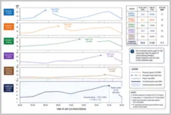
Load curves for five 34.5 kV feeders stacked over 24 hours with a combined system curve. The feeders peak between 24.2 MW and 10.6 MW at different times, and the combined peak is 95.8 MW at 21:00, a diversity factor of about 1.12.

House Service and Major Electrical Loads Labeled (thumbnail)🔒 All-Access

House Service and Major Electrical Loads Labeled

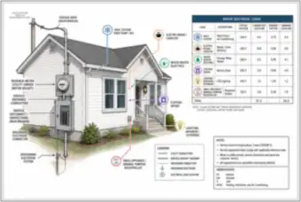
A single-family house with its service drop, meter, main panel and grounding electrode, with the major loads labeled and a table of connected and demand loads totaling 31.3 kW connected and 24.3 kW demand.

Two-Story House: Load Inventory and Single-Line Diagram (thumbnail)🔒 All-Access

Two-Story House: Load Inventory and Single-Line Diagram

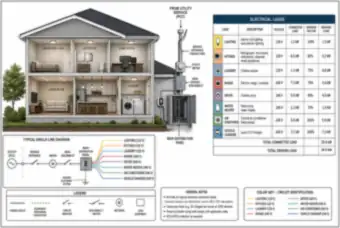
A cutaway two-story house with a table of lighting, kitchen, laundry, range, dryer, water heater, air conditioner and EV charger loads (35.4 kW connected, 29.9 kW demand), a simple single-line diagram and a color key.

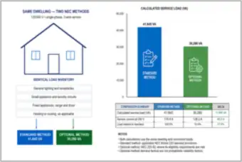
Dwelling Service Load: Standard Method vs. Optional Method (thumbnail)🔒 All-Access

Dwelling Service Load: Standard Method vs. Optional Method

The same dwelling calculated two ways under NEC Article 220: 41,845 VA (174.4 A) by the standard method and 30,280 VA (126.2 A) by the optional method, which is 27.6% lower, shown with a bar chart and comparison table.

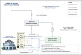
Commercial Building Service: Main Switchboard and Load Distribution (thumbnail)🔒 All-Access

Commercial Building Service: Main Switchboard and Load Distribution

A four-story office building on a 1000 A, 480Y/277 V service. The main switchboard feeds 480 V HVAC, elevator and kitchen loads, 277 V lighting, and a 225 kVA transformer to a 208Y/120 V receptacle and IT panel, with grounding and neutral notes.

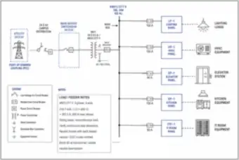
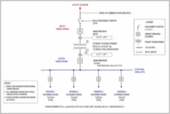
Commercial Single-Line Diagram: 34.5 kV Service to 480Y/277 V Panels (thumbnail)🔒 All-Access

Commercial Single-Line Diagram: 34.5 kV Service to 480Y/277 V Panels

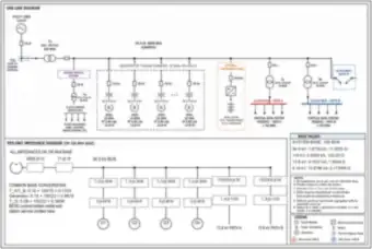
A single-line diagram from a 34.5 kV utility service through a main service switchgear and 34.5 kV-480Y/277 V transformer to lighting, HVAC, elevator, kitchen and IT room panels, with a 318.7 kVA, 383.3 A main sizing example.

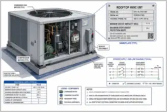
Rooftop HVAC Unit: Nameplate, MCA and MOCP (thumbnail)🔒 All-Access

Rooftop HVAC Unit: Nameplate, MCA and MOCP

A cutaway of a rooftop unit with its nameplate (460 V, three-phase, 70.0 A minimum circuit ampacity, 90 A maximum overcurrent protection), compressor and fan motor currents, a service disconnect and a power supply one-line.

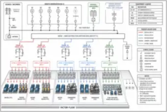
Factory Power Distribution: Generation, Feeders and Process Loads (thumbnail)🔒 All-Access

Factory Power Distribution: Generation, Feeders and Process Loads

A factory one-line with a utility service, five gas generators plus a spare (N+1), optional battery storage and a station service, feeding critical path A and B feeders to motors, process heaters, compressors and plant auxiliaries.

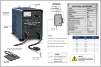
Industrial Arc Welder: Nameplate and Conductor Sizing (thumbnail)🔒 All-Access

Industrial Arc Welder: Nameplate and Conductor Sizing

A 480 V three-phase arc welder with a 500 A, 60% duty-cycle nameplate, a disconnect and supply connection. A 60 A input at a 0.78 multiplier gives a 46.8 A conductor basis, with a duty-cycle table and safety notes.

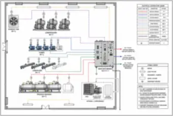
Plant Floor Layout: Compressors, Pumps, Conveyors and Process Heaters (thumbnail)🔒 All-Access

Plant Floor Layout: Compressors, Pumps, Conveyors and Process Heaters

A plant floor layout fed from a 480Y/277 V main switchboard, with compressors, pumps, conveyors, process heaters and an exhaust fan shown with spare (N+1) units, critical feeders A and B, a station service feeder and optional battery and black-start generator.

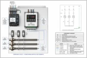
Three-Phase Process Heater Bank: Contactor, Power Controller and Fuses (thumbnail)🔒 All-Access

Three-Phase Process Heater Bank: Contactor, Power Controller and Fuses

A 480 V three-phase heater panel with a three-pole contactor, an SCR power controller, fuses, three heating elements and temperature sensors, shown as a component layout beside its schematic, a component summary and notes.

Hourly Demand Bar Chart: 180 kW Peak, 120 kW Average and 66.7% Load Factor (thumbnail)🔒 All-Access

Hourly Demand Bar Chart: 180 kW Peak, 120 kW Average and 66.7% Load Factor

A 24-hour demand chart with eight hours at 180 kW and sixteen at 90 kW, with the average demand of 120 kW, a daily energy of 2,880 kWh and a load factor of 120 ÷ 180 = 66.7%.

Step Load Profile: Daily Energy as the Area Under the Curve (thumbnail)🔒 All-Access

Step Load Profile: Daily Energy as the Area Under the Curve

A two-step 24-hour load profile (180 kW for 8 hours, then 90 kW for 16 hours) showing that daily energy is the area under the curve, 1,440 kWh in each period for 2,880 kWh in total, with a daily energy summary table.

Monthly Electricity Bill: Time-of-Use Energy and Demand Charges (thumbnail)🔒 All-Access

Monthly Electricity Bill: Time-of-Use Energy and Demand Charges

An annotated large-power electricity bill for a 34.5 kV service with on-peak and off-peak energy blocks, an energy cost adjustment, a $3,000,000 demand charge (200,000 kW at $15.00), transmission and distribution charges, a power factor credit and a $12,830,751.74 total.

Conductors, Branch Circuits & Voltage Drop

Ampacity, conduit fill, pull boxes, branch circuits, feeders and voltage drop
18 drawings
Copper vs. Aluminum Conductors: Construction, Temperature Ratings and Ambient Correction (thumbnail)🔒 All-Access

Copper vs. Aluminum Conductors: Construction, Temperature Ratings and Ambient Correction

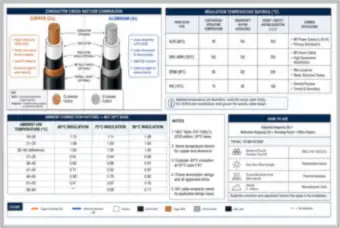
A cross-section comparison of copper and aluminum cables, insulation temperature ratings for XLPE, EPR, EPDM and PVC, the NEC ambient temperature correction table on a 30°C base, and how to apply derating and adjustment factors.

Rooftop Conduit with Six Conductors: Ambient and Fill Adjustment (thumbnail)🔒 All-Access

Rooftop Conduit with Six Conductors: Ambient and Fill Adjustment

A rigid metal conduit in direct sun carrying six current-carrying conductors plus a ground. A 0.91 ambient factor at 40°C and a 0.80 adjustment for six conductors give a combined 0.728 factor applied to the 90°C ampacity.

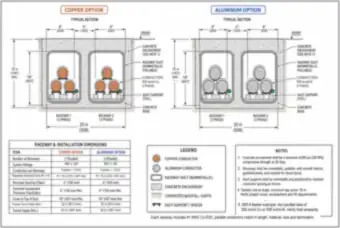
Parallel Raceways in a Concrete-Encased Duct Bank: Copper vs. Aluminum (thumbnail)🔒 All-Access

Parallel Raceways in a Concrete-Encased Duct Bank: Copper vs. Aluminum

A section of two parallel 480 V raceways in a concrete-encased duct bank, comparing 350 kcmil copper with 500 kcmil aluminum for a 600 A feeder, with the duct dimensions, cover, installation notes and a dimension table.

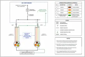
Two Parallel Conduits: Phase Conductors and Equipment Grounds (thumbnail)🔒 All-Access

Two Parallel Conduits: Phase Conductors and Equipment Grounds

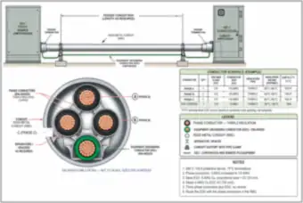
A 480 V switchboard feeding two parallel conduit sets, each with its own phase A, B and C conductors and an equipment grounding conductor, with a conductor schedule, legend and notes on terminating the sets in parallel.

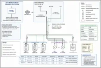
120 V Branch Circuit on a 208Y/120 V System: Receptacles, Lighting and Appliance Outlet (thumbnail)🔒 All-Access

120 V Branch Circuit on a 208Y/120 V System: Receptacles, Lighting and Appliance Outlet

A 20 A, single-pole branch circuit from a 208Y/120 V panelboard wired in 12 AWG copper in EMT, serving general-use receptacles, LED luminaires and an appliance outlet, with a circuit table, requirements, color coding and AFCI and GFCI notes.

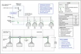
Lighting Circuit with LED Troffers: Continuous Load Limit (thumbnail)🔒 All-Access

Lighting Circuit with LED Troffers: Continuous Load Limit

A 120 V lighting circuit of 25 LED troffers at 30 W each on a 20 A breaker, with a 750 W, 6.25 A load against an 80% continuous-load limit of 16 A, shown as a one-line, a ceiling wiring layout and a load calculation.

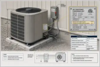
Outdoor Air-Conditioning Condensing Unit: Nameplate, MCA and MOCP (thumbnail)🔒 All-Access

Outdoor Air-Conditioning Condensing Unit: Nameplate, MCA and MOCP

An outdoor condensing unit with a nameplate showing 24.6 A minimum circuit ampacity and 40 A maximum overcurrent protection, a service disconnect, an electrical requirements table (60 A disconnect, #10 AWG copper) and a power supply sketch.

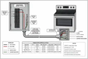
12 kW Electric Range: 50 A Branch Circuit and Four-Wire Connection (thumbnail)🔒 All-Access

12 kW Electric Range: 50 A Branch Circuit and Four-Wire Connection

A 12 kW, 120/240 V electric range on a 50 A two-pole breaker with a four-wire cable (two hots, neutral and ground), a terminal block showing the unused terminal, and a copper conductor schedule using #6 AWG and a #10 AWG ground.

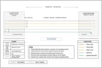
Feeder from a Distribution Panel: Phases, Neutral and Equipment Ground (thumbnail)🔒 All-Access

Feeder from a Distribution Panel: Phases, Neutral and Equipment Ground

A feeder from a 480Y/277 V, 400 A distribution panel through a 225 A three-pole breaker to a downstream panel, with the neutral bonded to ground only at the source, a color code legend and notes on isolating the neutral downstream.

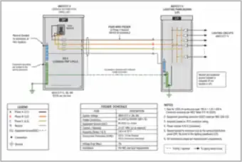
480Y/277 V Distribution Panel Feeding a Lighting Panelboard (thumbnail)🔒 All-Access

480Y/277 V Distribution Panel Feeding a Lighting Panelboard

A 200 A distribution panel feeding a lighting panelboard with four 4/0 copper conductors in 2-1/2 in. RMC, sized for 125% of a 160 A continuous load, with the neutral bond location, a feeder schedule and installation notes.

Long Medium-Voltage Cable Run: Voltage Profile Over 8,000 ft (thumbnail)🔒 All-Access

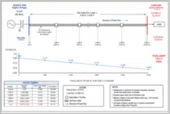
Long Medium-Voltage Cable Run: Voltage Profile Over 8,000 ft

An 8,000 ft, 13.8 kV run of 500 kcmil copper cable carrying 209.2 A at 0.90 power factor, with the voltage falling from 13.800 kV to 13.685 kV, a total drop of 114.7 V (0.83%), shown as a profile chart and a table by distance.

Long 120 V Branch Circuit to an Outbuilding: 14.48% Voltage Drop (thumbnail)🔒 All-Access

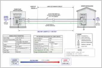
Long 120 V Branch Circuit to an Outbuilding: 14.48% Voltage Drop

A 300 ft, 20 A branch circuit in 12 AWG copper carrying 15 A to a remote outbuilding. The calculation gives a 17.37 V drop (14.48%), leaving 102.6 V at the load, well over the 3% design limit, so the conductors need enlarging or the run shortening.

480 V Feeder Over 300 ft: Copper vs. Aluminum Comparison (thumbnail)🔒 All-Access

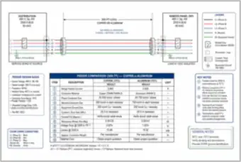
480 V Feeder Over 300 ft: Copper vs. Aluminum Comparison

A 2000 A, 480 V feeder run in six parallel raceways, comparing 500 kcmil copper with 750 kcmil aluminum for voltage drop (0.93% vs. 1.02%) and losses (15.48 kW vs. 16.92 kW), with the design basis and key notes.

Line Drop Phasor Diagram: Resistive and Reactive Drops (thumbnail)🔒 All-Access

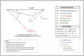
Line Drop Phasor Diagram: Resistive and Reactive Drops

A phasor diagram of sending voltage, receiving voltage and a lagging line current, showing the resistive drop RI in phase with current and the reactive drop jXI leading it by 90°, with definitions and the relationship VR = VS − ΔV.

Conduit Bend Vault: Conduits, Sweeps and Backfill Details (thumbnail)🔒 All-Access

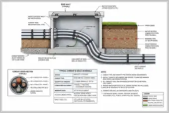
Conduit Bend Vault: Conduits, Sweeps and Backfill Details

A bend vault with three parallel rigid conduits making a long-sweep 90° bend, with a conduit cross-section showing three phase conductors, neutral and ground, a conduit and vault schedule, backfill and cover details and installation notes.

EMT Conduit Fill Calculation: Four 350 kcmil Conductors and a Bonding Wire (thumbnail)🔒 All-Access

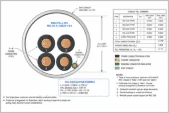
EMT Conduit Fill Calculation: Four 350 kcmil Conductors and a Bonding Wire

A cross-section of 2-1/2 in. EMT holding four 350 kcmil THHN conductors and a 4 AWG bonding conductor. Total conductor area of 2.1792 in² against a 5.858 in² conduit gives 37.2% fill, within the 40% limit, with the table and calculation shown.

Short EMT Run with Ten 12 AWG Conductors and a Junction Box (thumbnail)🔒 All-Access

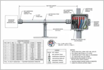
Short EMT Run with Ten 12 AWG Conductors and a Junction Box

A 3 ft run of 3/4 in. EMT between raintight connectors and a NEMA 4X junction box, carrying ten 12 AWG circuit conductors and a ground (27.5% fill against a 40% limit), with a conductor schedule, support spacing and notes.

Pull Box Sizing: Straight Pull and Angle Pull (thumbnail)🔒 All-Access

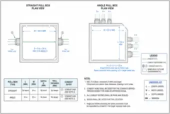
Pull Box Sizing: Straight Pull and Angle Pull

Plan views of a straight pull box (24 in. minimum from 8 × 3 in. trade size) and an angle pull box (22 in. from 6 × 3 + 2 + 2), with the NEC 314.28 sizing rules, conduit hub notes and a dimension table.

Services, Panels & Buildings

Service entrances, panelboards, switchboards, residential and commercial building power
17 drawings
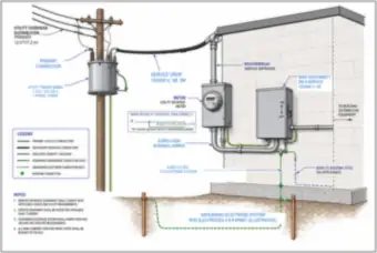
Utility Transformer, Service Drop, Meter and Main Disconnect (thumbnail)🔒 All-Access

Utility Transformer, Service Drop, Meter and Main Disconnect

A pole-mounted 7.2 kV to 120/240 V transformer feeding an overhead service drop to a weatherhead, meter and 200 A main disconnect, with the main bond, supply-side bonding jumper, grounding electrode conductor and ground rods labeled.

House Service Entrance: Weatherhead, Meter, Disconnect and Grounding Electrode (thumbnail)🔒 All-Access

House Service Entrance: Weatherhead, Meter, Disconnect and Grounding Electrode

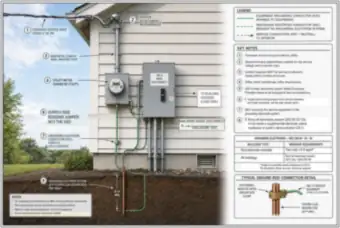
A house exterior showing the overhead service drop, conduit, meter, 200 A main disconnect, supply-side bonding jumper, a 4 AWG copper grounding electrode conductor and an 8 ft ground rod, with key notes, an electrode requirements table and a rod connection detail.

Commercial Electrical Room: 400 A Main Switchboard, Plan and Elevation (thumbnail)🔒 All-Access

Commercial Electrical Room: 400 A Main Switchboard, Plan and Elevation

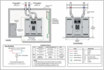
A 400 A, 480Y/277 V main switchboard in an electrical room with two parallel service conduits, working space clearances, a 2 AWG grounding electrode conductor, plan and elevation views, a one-line diagram and an equipment schedule.

1,000 A Service: Transformer to Switchgear with Three Parallel Sets per Phase (thumbnail)🔒 All-Access

1,000 A Service: Transformer to Switchgear with Three Parallel Sets per Phase

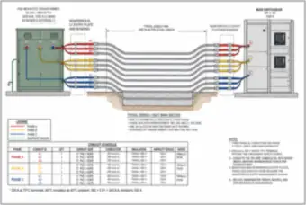
A 1000 kVA, 34.5 kV to 480Y/277 V pad-mounted transformer feeding 1000 A main switchgear through nine 5 in. nonmetallic raceways, three per phase, each with 400 kcmil copper at 335 A, with a conduit schedule and trench section.

Panelboard Interior: Bus, Breakers, Neutral and Ground Bars (thumbnail)🔒 All-Access

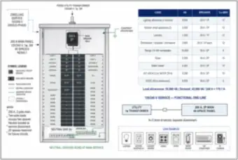
Panelboard Interior: Bus, Breakers, Neutral and Ground Bars

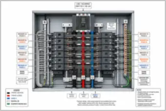
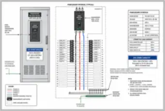
The inside of a 208Y/120 V, 400 A panelboard showing the main breaker, phase bus stabs, branch breakers arranged by phase, the isolated neutral bar and the ground bar, with ratings, notes and a legend.

Panelboard Phase Balance: Breakers Alternating Across A, B and C (thumbnail)🔒 All-Access

Panelboard Phase Balance: Breakers Alternating Across A, B and C

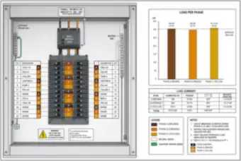
A 480Y/277 V, 2000 A panel with breakers alternating across the three phases and a circuit directory, with a load-per-phase chart (306, 299 and 310.5 kW against a 305.2 kW average) and a load summary table.

208Y/120 V Panelboard: Main Breaker, Schedule and 25% Spare Capacity (thumbnail)🔒 All-Access

208Y/120 V Panelboard: Main Breaker, Schedule and 25% Spare Capacity

A 400 A panelboard with a 300 A connected load leaving 100 A, or 25%, spare. It shows the main breaker, branch breakers for panels, HVAC, lighting and receptacles, a panelboard schedule and the spare capacity calculation.

Neutral Bar Current in a 208Y/120 V Panelboard: 79.4 A Vector Sum (thumbnail)🔒 All-Access

Neutral Bar Current in a 208Y/120 V Panelboard: 79.4 A Vector Sum

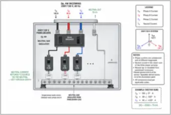
A panelboard with phase currents of 150 A, 90 A and 60 A and a 79.4 A neutral current found as the vector sum, with the insulated neutral bar, single-phase loads on each phase, a phasor view and notes on where the neutral is bonded.

3,000 sq ft House: Major Electrical Loads and One-Line (thumbnail)🔒 All-Access

3,000 sq ft House: Major Electrical Loads and One-Line

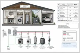
A cutaway of a 3,000 sq ft single-family house showing a 12 kVA range, 5 kVA dryer, 4.5 kVA water heater, 5.76 kVA heat pump and 9.6 kVA EV charger (36.86 kVA connected), with a 120/240 V service one-line and circuit breakers.

200 A Main Panel: Circuit Layout, Load Schedule and 179.1 A Demand (thumbnail)🔒 All-Access

200 A Main Panel: Circuit Layout, Load Schedule and 179.1 A Demand

A 200 A, 40-space 120/240 V main panel with its circuit directory, a load schedule of lighting, appliances, range, dryer, water heater, A/C and EV charger (55,980 VA allowances, 42,980 VA demand, 179.1 A), breaker and wire sizes, and the neutral-ground bond.

Residential Service Entrance and Underground Branch Circuits to an EV Charger and A/C (thumbnail)🔒 All-Access

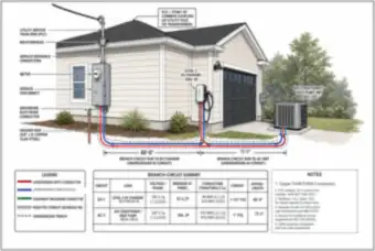
Residential Service Entrance and Underground Branch Circuits to an EV Charger and A/C

A house exterior with a weatherhead, meter, service disconnect and ground rod, and underground PVC branch circuits of 60 ft to a 50 A EV charger (#6 AWG) and 75 ft to a 30 A air conditioner (#10 AWG), with a branch circuit summary.

Residential One-Line: Utility Transformer to a 200 A Panelboard and Grounding (thumbnail)🔒 All-Access

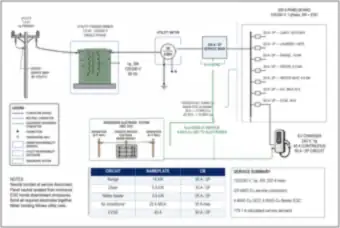
Residential One-Line: Utility Transformer to a 200 A Panelboard and Grounding

A one-line from a 7.2 kV pole transformer through the meter and a 200 A main to a panelboard with range, dryer, water heater, A/C and EV circuits, with the grounding electrode system, a 4 AWG GEC, a 2/0 AWG service conductor and a 179.1 A calculated demand.

Four-Story Office Building Elevation: Electrical, Data and Elevator Rooms (thumbnail)🔒 All-Access

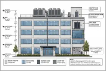
Four-Story Office Building Elevation: Electrical, Data and Elevator Rooms

An elevation of a 60,000 sq ft, four-story office building with floor elevations, rooftop HVAC, an elevator machine room, a data room and a main electrical room at grade serving a 480Y/277 V, 1,000 A service.

Main Switchboard Feeding a 225 kVA Transformer and 208 V Distribution Panel (thumbnail)🔒 All-Access

Main Switchboard Feeding a 225 kVA Transformer and 208 V Distribution Panel

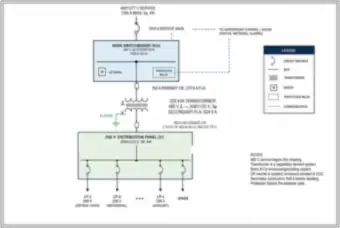
A one-line from a 480Y/277 V, 1,000 A main switchboard through a 350 A primary breaker, a 225 kVA delta-wye transformer (270.6 A primary, 624.5 A secondary) and an 800 A secondary breaker to a 208Y/120 V distribution panel and lighting panels.

Office Building Riser: Main Switchboard, Feeders and Available Fault Current (thumbnail)🔒 All-Access

Office Building Riser: Main Switchboard, Feeders and Available Fault Current

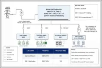
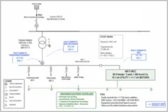
A riser diagram of a 480Y/277 V, 1,000 A main switchboard with 20.1 kA available fault current feeding HVAC, lighting and elevator panels and a 225 kVA transformer to a 208Y/120 V distribution panel at 9.9 kA, with a fault table and notes.

Standby Generator Sizing with Life-Safety, Elevator and IT Transfer Switches (thumbnail)🔒 All-Access

Standby Generator Sizing with Life-Safety, Elevator and IT Transfer Switches

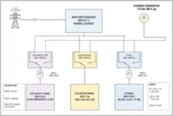
A 480Y/277 V main switchboard and a standby generator feeding three transfer switches for life-safety (35 kW), elevator (28.3 kW) and IT (57 kW) loads. The 120.3 kW total divided by 0.80 gives 150.4 kW, so a 175 kW generator is selected.

Motor Control Center Elevation with Bucket Labels and Starter Schedule (thumbnail)🔒 All-Access

Motor Control Center Elevation with Bucket Labels and Starter Schedule

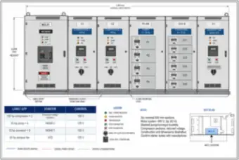
A 3,600 mm wide, six-section motor control center with a 1000 A main, two 100 hp compressors, four 30 hp pumps, six 10 hp conveyors and a 50 hp VFD exhaust fan, with a starter and control schedule and a key plan.

Transformers

Cutaways, turns ratio, three-phase connections, efficiency, parallel operation and protection
8 drawings
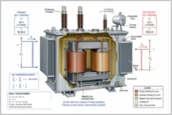
Oil-Filled Transformer Cutaway: Core, Windings and Components (thumbnail)🔒 All-Access

Oil-Filled Transformer Cutaway: Core, Windings and Components

A cutaway of a 25 kVA, 480/120 V single-phase oil-filled transformer showing the laminated core, primary and secondary windings, bushings, conservator, radiators and drain valve, with turns ratio relationships and full-load currents (52.08 A and 208.3 A).

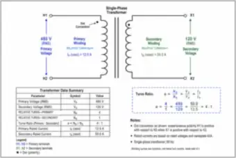
Single-Phase Transformer: 480 V to 120 V Turns Ratio and Dot Convention (thumbnail)🔒 All-Access

Single-Phase Transformer: 480 V to 120 V Turns Ratio and Dot Convention

A single-phase transformer with a 480 V primary and 120 V secondary, a 4:1 turns ratio, rated currents of 12.5 A and 50.0 A, the polarity dot convention, a data summary table and the turns-ratio formula.

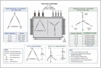
Three-Phase Delta-Wye Transformer: 480 V Delta to 208Y/120 V (thumbnail)🔒 All-Access

Three-Phase Delta-Wye Transformer: 480 V Delta to 208Y/120 V

A three-phase transformer with a 480 V delta primary and a 208Y/120 V wye secondary with grounded neutral, with terminal tables for each side, line-to-line and line-to-neutral voltages, the 30° phase shift and the Dyn1 vector group.

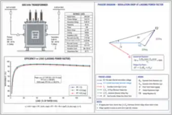
500 kVA Transformer: Ratings, Efficiency Curve and Regulation Phasors (thumbnail)🔒 All-Access

500 kVA Transformer: Ratings, Efficiency Curve and Regulation Phasors

A 500 kVA, 34.5 kV to 0.48 kV transformer with its ratings (5.75% impedance, 1.10 kW no-load loss, 6.20 kW load loss), efficiency-versus-load curves at three power factors, a peak efficiency at 42.1% load, and a regulation phasor diagram.

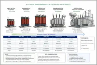
Transformer Types by Size: Dry-Type to Liquid-Filled Unit Substation (thumbnail)🔒 All-Access

Transformer Types by Size: Dry-Type to Liquid-Filled Unit Substation

Five transformer types from a 15 kVA dry-type unit to a 2.5 MVA liquid-filled unit substation, compared by capacity, primary and secondary voltage, cooling and application, with key considerations and selection drivers.

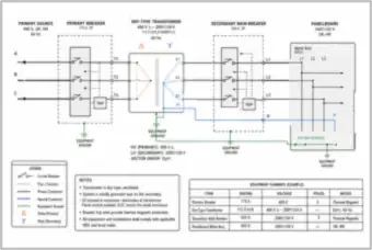
480 V to 208Y/120 V Dry-Type Transformer: Primary and Secondary Protection (thumbnail)🔒 All-Access

480 V to 208Y/120 V Dry-Type Transformer: Primary and Secondary Protection

A one-line of a 112.5 kVA dry-type delta-wye transformer with a 175 A primary breaker, a 400 A secondary main breaker and a panelboard, showing the X0 bond, equipment grounds, the Dyn1 vector group and an equipment summary.

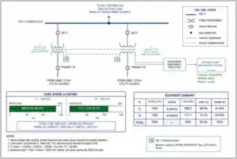
Two Transformers in Parallel: Load Sharing by Rating and Impedance (thumbnail)🔒 All-Access

Two Transformers in Parallel: Load Sharing by Rating and Impedance

A 1000 kVA (5% impedance) and a 1500 kVA (6%) transformer in parallel on a 480 V bus carrying 2000 kVA. The units take 44.44% and 55.56% of the load, giving a 2250 kVA parallel capacity limited by the smaller unit.

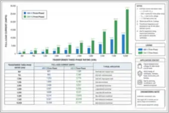
Transformer Full-Load Current: 480 V and 208 V, 500 kVA to 10,000 kVA (thumbnail)🔒 All-Access

Transformer Full-Load Current: 480 V and 208 V, 500 kVA to 10,000 kVA

A bar chart and table of full-load current for three-phase transformers from 500 kVA to 10,000 kVA at 480 V and 208 V (for example 1,203 A and 2,776 A at 1,000 kVA), with the formula I = S / (√3 × V), notes and typical applications.

Motors & Drives

Induction motors, starting, branch circuits, VFDs, line reactors and fan energy
13 drawings
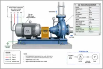
25 hp Three-Phase Motor Driving a Pump, with Nameplate (thumbnail)🔒 All-Access

25 hp Three-Phase Motor Driving a Pump, with Nameplate

A 25 hp, 460 V three-phase induction motor coupled to a centrifugal pump, with the nameplate values (29.0 A full-load current, 1770 rpm, 92.4% efficiency, 0.89 power factor), the supply connection and a power-flow sketch.

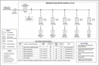
Medium-Voltage Motor Control at 4.16 kV: Soft Starters and Feeder Schedule (thumbnail)🔒 All-Access

Medium-Voltage Motor Control at 4.16 kV: Soft Starters and Feeder Schedule

A 4.16 kV motor control center fed from a 34.5 kV source through a 400 A incomer breaker, with five soft-started motors (pumps and cooling tower fans, 200 to 300 hp), overload relays, a current transformer and a feeder and motor schedule.

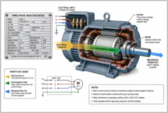
Three-Phase Induction Motor Cutaway: Nameplate and Power Flow (thumbnail)🔒 All-Access

Three-Phase Induction Motor Cutaway: Nameplate and Power Flow

A cutaway of a 300 hp, 4160 V, four-pole induction motor showing the stator and rotor, with the nameplate (37.0 A, 1775 rpm, 95.4% efficiency), the flow from electrical power in to mechanical power out, and the supply connection.

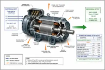
50 hp Motor Cutaway: Power Flow and Losses (thumbnail)🔒 All-Access

50 hp Motor Cutaway: Power Flow and Losses

A cutaway of a 50 hp, 460 V motor showing 40.11 kW of electrical input and 37.3 kW of shaft output (93.0% efficiency), with each loss labeled (stator copper, rotor copper, core, friction, windage and stray load) and a power flow summary table.

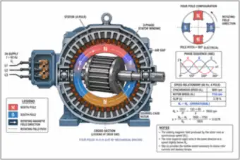
Four-Pole Induction Motor Cross-Section: Rotating Field, Speed and Slip (thumbnail)🔒 All-Access

Four-Pole Induction Motor Cross-Section: Rotating Field, Speed and Slip

A cross-section of a four-pole squirrel-cage induction motor showing the stator windings, air gap and rotor, the rotating field and phase sequence, and the speed relationship: 1800 rpm synchronous, 1750 rpm rotor and 2.78% slip.

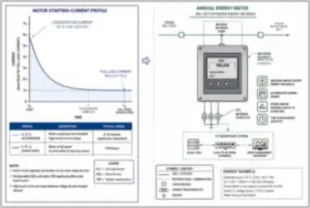
Motor Starting Current Profile and Annual Energy Metering (thumbnail)🔒 All-Access

Motor Starting Current Profile and Annual Energy Metering

A starting current curve for a 50 hp motor from 5.8 times full-load current (377 A) down to the 65 A running current, beside an energy meter on the 480 V feeder showing 160,430 kWh a year from 40.11 kW over 4,000 hours.

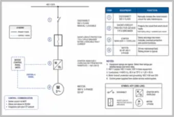
Motor Branch Circuit One-Line: Disconnect, 175 A Breaker, Starter and Motor (thumbnail)🔒 All-Access

Motor Branch Circuit One-Line: Disconnect, 175 A Breaker, Starter and Motor

A one-line for a 50 hp, 460 V motor with a lockable disconnect, a 175 A short-circuit protective breaker, a NEMA size 3 starter with overload and the motor, with an equipment function table, conductor sizing note and control signals to SCADA.

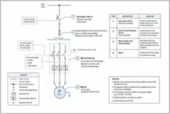
Motor Branch Circuit Detail: Disconnect, Short-Circuit Device, Contactor and Overload Relay (thumbnail)🔒 All-Access

Motor Branch Circuit Detail: Disconnect, Short-Circuit Device, Contactor and Overload Relay

A detailed motor branch circuit showing the visible-open disconnect, a fuse or molded-case breaker, a magnetic contactor with thermal overload relays, the control coil and a 50 hp motor, with SCADA status signals and notes tied to NEC 430.

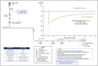
Motor Starting on a Long Feeder: Voltage Dip at the Motor Terminals (thumbnail)🔒 All-Access

Motor Starting on a Long Feeder: Voltage Dip at the Motor Terminals

A 50 hp, 460 V motor starting at 390 A on a long feeder. The terminal voltage dips about 5.1% (23.7 V) at start and recovers as the motor accelerates, with the source bus holding 1.00 per unit, shown on a voltage-time curve.

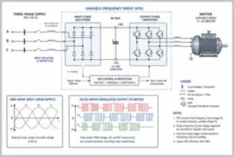
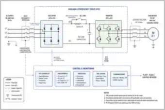
Variable Frequency Drive: Rectifier, DC Link and Inverter Block Diagram (thumbnail)🔒 All-Access

Variable Frequency Drive: Rectifier, DC Link and Inverter Block Diagram

A 480 V VFD block diagram with an input reactor, rectifier, DC link capacitor, IGBT inverter and control section, driving a variable-speed motor, with the sine-wave input and PWM output waveforms compared and notes on drive operation.

VFD for a 50 hp Fan Motor: Protection, Control and Monitoring (thumbnail)🔒 All-Access

VFD for a 50 hp Fan Motor: Protection, Control and Monitoring

A 480 V variable frequency drive for a 50 hp fan motor with input disconnect and 5% reactor, precharge bypass contactor, rectifier, inverter and optional output filter, with controller, measurements, protections, keypad and SCADA communications.

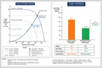
Fan and System Curves: VFD Speed Control vs. Damper Throttling (thumbnail)🔒 All-Access

Fan and System Curves: VFD Speed Control vs. Damper Throttling

Fan curves at 100%, 80%, 60% and 40% speed against a system curve, and a comparison at 80% airflow: damper throttling uses 90% of full input power and VFD speed control 51.2%, a 43.1% saving.

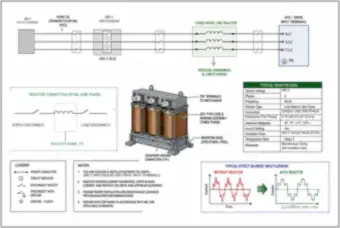
Three-Phase Line Reactor Ahead of a VFD (thumbnail)🔒 All-Access

Three-Phase Line Reactor Ahead of a VFD

A 5% line reactor (0.70 mH at 52.4 A) installed between 480 V switchgear and the drive input terminals, with a reactor assembly view, typical data, and a comparison of input current with and without the reactor (illustrative 35% THD).

Generators, UPS & Transfer Switches

Standby generators, paralleling, fuel, automatic transfer switches and UPS architectures
12 drawings
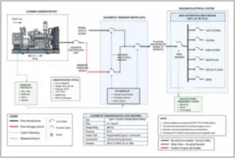
Standby Generator Set with Automatic Transfer Switch and Building Distribution (thumbnail)🔒 All-Access

Standby Generator Set with Automatic Transfer Switch and Building Distribution

A one-line of a diesel standby generator feeding an automatic transfer switch alongside the utility source, then a main distribution switchboard serving HVAC, lighting, pumps, receptacles and critical IT loads, with ATS features and notes.

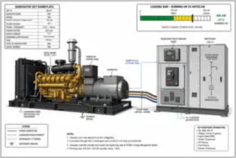
Standby Diesel Generator: Nameplate and Loading (thumbnail)🔒 All-Access

Standby Diesel Generator: Nameplate and Loading

A 500 kW standby diesel generator set (480 V, 752 A, 0.8 power factor) connected through a generator breaker to 480 V switchgear, with a loading bar showing 400 kW running (80%), key monitored parameters and notes.

Generator Voltage Dip When a Large Motor Starts (thumbnail)🔒 All-Access

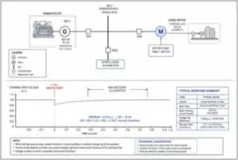
Generator Voltage Dip When a Large Motor Starts

A 500 kVA, 0.8 power factor generator (X″d = 0.25 pu) starting a 450 kVA motor on its bus. The terminal voltage falls to 0.816 per unit (18.4% dip) and then recovers, shown on a voltage-time plot with a response summary.

Skid-Mounted Diesel Fuel Tank: Usable Fuel and Runtime (thumbnail)🔒 All-Access

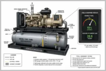
Skid-Mounted Diesel Fuel Tank: Usable Fuel and Runtime

A diesel generator on a skid-mounted fuel tank with secondary containment, sight gauge and low-level shutoff, plus a controller display showing 65% usable fuel (741 gal) and 28.6 hours of runtime at a 375 kW load.

Three Generators in Parallel on a 34.5 kV Common Bus (thumbnail)🔒 All-Access

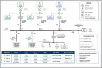
Three Generators in Parallel on a 34.5 kV Common Bus

Three 13.8 kV generators with step-up transformers on a 34.5 kV common bus, with two online sharing about 50% each and one synchronized standby, feeding two critical data center feeders and a station-service transformer, with status and operating notes.

Transfer Switch Between Utility and Generator: Positions and Controller (thumbnail)🔒 All-Access

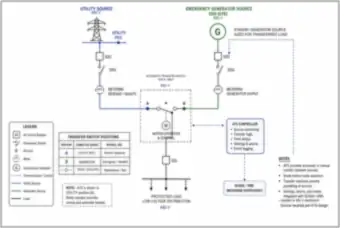
Transfer Switch Between Utility and Generator: Positions and Controller

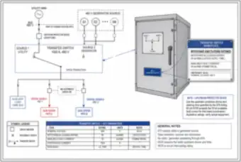
A 1000 A, 480 V automatic transfer switch between a utility source and an emergency generator, with metering, a motor operator and controller, a table of switch positions (utility, generator, open) and notes on break-before-make transfer.

Automatic Transfer Switch for a Data Center Campus Load (thumbnail)🔒 All-Access

Automatic Transfer Switch for a Data Center Campus Load

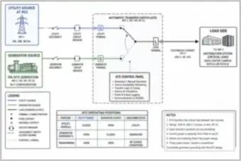
A 1000 A, 480 V automatic transfer switch moving a critical load between the utility and an N+1 generator source, with disconnects, breakers, a control panel and a table of operating positions (utility, generator and transferring).

Transfer Switch Nameplate: Withstand and Closing Rating (thumbnail)🔒 All-Access

Transfer Switch Nameplate: Withstand and Closing Rating

A 1000 A, 480 V open-transition transfer switch with its nameplate showing a 65 kA withstand and closing rating against 35 kA available fault current, with the feeders to two data center paths and a key parameters table.

Generator with Three Transfer Switches: Life-Safety, Legally Required and Optional Loads (thumbnail)🔒 All-Access

Generator with Three Transfer Switches: Life-Safety, Legally Required and Optional Loads

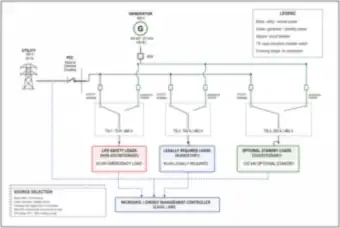
A 300 kW diesel generator feeding three open-transition transfer switches (70 A, 100 A and 200 A) for life-safety (45 kW), legally required (60 kW) and optional standby (120 kW) loads, with source selection notes and a microgrid or SCADA controller.

Double-Conversion UPS Block Diagram: Rectifier, Inverter, Battery and Bypasses (thumbnail)🔒 All-Access

Double-Conversion UPS Block Diagram: Rectifier, Inverter, Battery and Bypasses

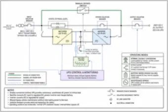
A 200 kVA double-conversion UPS with a rectifier, DC link, inverter, battery system and isolator, static and manual bypass paths and isolation breakers, with the four operating modes: normal, bypass, battery and maintenance bypass.

UPS Power Paths: Normal, Static Bypass and Maintenance Bypass (thumbnail)🔒 All-Access

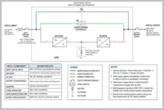
UPS Power Paths: Normal, Static Bypass and Maintenance Bypass

A 200 kVA, 200 kW UPS with its normal power path (rectifier, DC link, inverter), the automatic static bypass and the manual maintenance bypass, with a table of ratings per path and component and notes on how each path is used.

UPS Architectures Compared: Parallel N+1 vs. 2N Independent Paths (thumbnail)🔒 All-Access

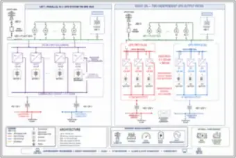
UPS Architectures Compared: Parallel N+1 vs. 2N Independent Paths

Two UPS arrangements side by side. On the left is a 4 × 120 kW parallel N+1 system on one bus. On the right is a 2N system with two independent 360 kW paths (A and B), with generators, station service and operating modes.

Batteries & Energy Storage

Battery strings and banks, station batteries, inverters and battery energy storage systems
9 drawings
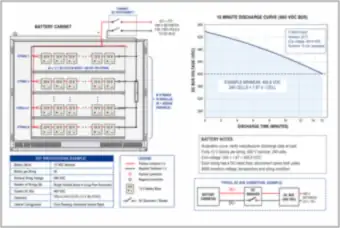
UPS Battery Cabinet: 480 V Strings and 15-Minute Discharge Curve (thumbnail)🔒 All-Access

UPS Battery Cabinet: 480 V Strings and 15-Minute Discharge Curve

A battery cabinet with strings of forty 12 V lead-acid blocks (480 V nominal), per-string fuses and a DC disconnect, with a 15-minute discharge curve ending at 400.8 VDC (240 cells at 1.67 V per cell) and a key specifications table.

Battery Bank Series and Parallel Connections: Voltage and Capacity (thumbnail)🔒 All-Access

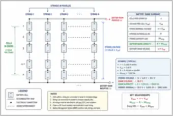
Battery Bank Series and Parallel Connections: Voltage and Capacity

A battery bank with cells in series per string and strings in parallel, with the relationships V = n × Vcell and Ah = N × Ahstring, and a worked example: 12 cells at 3.20 V and 8 strings of 1,200 Ah give 38.4 V, 9,600 Ah and 368.6 kWh.

48 V Battery Bank: Sixteen 12 V Blocks in Four Parallel Strings (thumbnail)🔒 All-Access

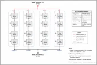
48 V Battery Bank: Sixteen 12 V Blocks in Four Parallel Strings

A 48 VDC battery bank built from sixteen 12 V blocks, as four parallel strings of four series blocks, each with its own DC-rated fuse, with a bank summary (capacity is four times the block capacity) and notes.

Substation Battery Room: 125 V Station Battery, Charger and DC Panel (thumbnail)🔒 All-Access

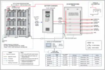
Substation Battery Room: 125 V Station Battery, Charger and DC Panel

A 125 VDC lead-acid station battery (60 × 2 V cells, about 148 Ah) with a float and equalize charger and a DC distribution panel feeding protective relays and breaker trip coils, with a DC circuit table and monitoring to SCADA.

48 V Battery Bank to Inverter: State of Charge and Runtime (thumbnail)🔒 All-Access

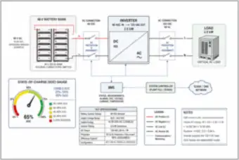
48 V Battery Bank to Inverter: State of Charge and Runtime

A 48 V, 400 Ah battery bank feeding a 2.5 kW inverter and AC load through DC and AC disconnects, with a state-of-charge gauge at 65%, a BMS, 14.59 kWh of usable energy and a 5.84 hour runtime calculation.

4 MW / 16 MWh Battery Energy Storage Plant: Interconnection One-Line (thumbnail)🔒 All-Access

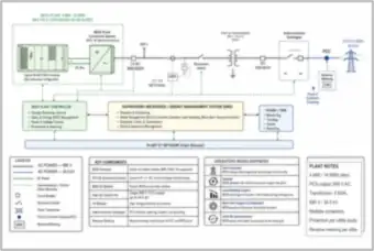
4 MW / 16 MWh Battery Energy Storage Plant: Interconnection One-Line

A 4 MW, 16 MWh battery energy storage plant with a power conversion system, 690 V breaker, a 5 MVA step-up transformer to 34.5 kV, interconnection switchgear and revenue metering, with the plant controller, EMS, SCADA and operating modes.

Battery Energy Storage Container: Racks, PCS and Medium-Voltage Switchgear (thumbnail)🔒 All-Access

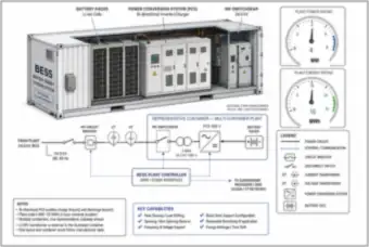
Battery Energy Storage Container: Racks, PCS and Medium-Voltage Switchgear

A cutaway of a containerized battery energy storage system showing lithium-ion racks, a bidirectional power conversion system and 34.5 kV switchgear, with a one-line, 4 MW and 16 MWh rating gauges and key capabilities.

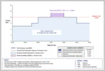
Peak Shaving with Battery Storage: 16 MW Demand Limit (thumbnail)🔒 All-Access

Peak Shaving with Battery Storage: 16 MW Demand Limit

A daily campus load profile with a 19 MW peak above a 16 MW demand limit, where a 3 MW battery discharges for 4 hours (12 MWh) from 12:00 to 16:00 to hold the grid or generation at or below the limit.

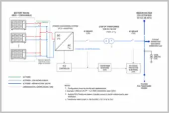
Battery Racks to Medium-Voltage Bus: PCS, Step-Up Transformer and Collector (thumbnail)🔒 All-Access

Battery Racks to Medium-Voltage Bus: PCS, Step-Up Transformer and Collector

A one-line of battery racks, a DC combiner and a power conversion system feeding a 5 MVA, 0.69/34.5 kV step-up transformer and a 34.5 kV collector bus, with a 4 MW at 0.95 power factor example (4.21 MVA, 4,184 A at 690 V and 83.7 A at 34.5 kV).

Short-Circuit & Per-Unit Studies

Fault calculations, source contributions, equipment ratings and the per-unit system
19 drawings
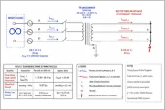
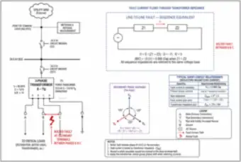
Line-to-Line Fault at Transformer Secondary Terminals (thumbnail)🔒 All-Access

Line-to-Line Fault at Transformer Secondary Terminals

A 60 MVA, 7.0% impedance delta-wye transformer with a bolted fault between phases B and C on the secondary, with the sequence-network equivalent, the fault current relationship (√3 times the positive-sequence current) and secondary phase voltages before the fault.

Bolted Three-Phase Fault at a 1000 kVA Transformer: 20.1 kA (thumbnail)🔒 All-Access

Bolted Three-Phase Fault at a 1000 kVA Transformer: 20.1 kA

A 1000 kVA, 6.0% impedance transformer on an infinite source with a bolted three-phase fault on the secondary. The fault is 16.67 per unit, or about 20.1 kA, with a primary line current of about 279 A, shown with a fault current table.

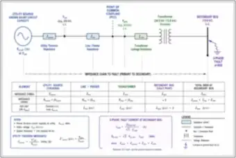
Impedance Chain from Utility Source to a 13.8 kV Fault (thumbnail)🔒 All-Access

Impedance Chain from Utility Source to a 13.8 kV Fault

The impedance path from a utility source with known short-circuit capacity through the line and a 34.5/13.8 kV transformer to a three-phase fault on the secondary bus, with the Thevenin impedance formulas and the fault current and MVA equations.

Motor Contribution to Fault Current on a 480 V Bus (thumbnail)🔒 All-Access

Motor Contribution to Fault Current on a 480 V Bus

A 1500 kVA transformer feeding a 480 V plant bus where three running 400 hp motors add fault current. The transformer supplies 31.38 kA and each motor 1.984 kA, for 37.33 kA total, with the fault current paths and notes on decay.

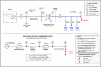
Bolted Three-Phase Fault: One-Line and Equivalent Impedance Diagram (thumbnail)🔒 All-Access

Bolted Three-Phase Fault: One-Line and Equivalent Impedance Diagram

A utility source, step-down transformer and 480 V cable to a bolted fault, drawn as a one-line and as a per-phase impedance circuit with the formulas I_f = E_s / (Z_s + Z_t + Z_c) and Z_eq = ΣR + jΣX, and a table defining each term.

Fault Calculation: 1,000 kVA Transformer and Parallel Cables, 19.92 kA (thumbnail)🔒 All-Access

Fault Calculation: 1,000 kVA Transformer and Parallel Cables, 19.92 kA

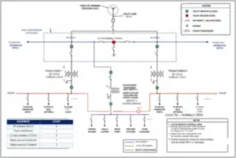
A 12.47 kV/480 V, 1,000 kVA transformer (5.75% impedance, X/R of 5) with three parallel 500 kcmil copper conductors per phase over 50 ft to a switchboard. The total impedance of 13.912 mΩ gives a 19.92 kA bolted three-phase fault.

Fault Types on a 34.5 kV Bus: Three-Phase, Line-to-Line and Line-to-Ground (thumbnail)🔒 All-Access

Fault Types on a 34.5 kV Bus: Three-Phase, Line-to-Line and Line-to-Ground

A 34.5 kV main bus fed by the utility, N+1 generators and optional battery storage, with the three-phase, line-to-line and single line-to-ground fault types marked at one location, feeding two critical paths and a station-service feeder.

Combining Utility and Transformer Fault MVA at a Secondary Bus (thumbnail)🔒 All-Access

Combining Utility and Transformer Fault MVA at a Secondary Bus

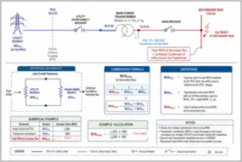
A utility source and 100 MVA, 11.11% impedance transformer feeding a 13.8 kV bus. The reciprocal combination formula turns 1,200 MVA from the utility and 900 MVA from the transformer into 514.3 MVA at the secondary bus.

Equipment Nameplates: Interrupting Ratings Compared with Available Fault Current (thumbnail)🔒 All-Access

Equipment Nameplates: Interrupting Ratings Compared with Available Fault Current

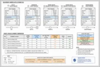
Nameplates for five 34.5 kV class circuit breakers (utility, generator, two feeders and station service) with a table comparing interrupting and short-time ratings to available fault current and showing the margin for each, with the design intent.

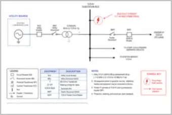
Fault Current Contributions at a 34.5 kV Bus: Utility, Generators and Battery (thumbnail)🔒 All-Access

Fault Current Contributions at a 34.5 kV Bus: Utility, Generators and Battery

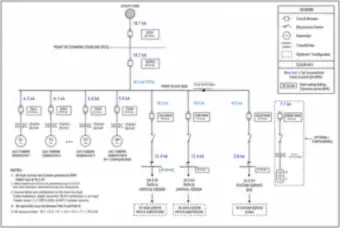
A one-line with fault current written at each point: 18.7 kA from the utility, four gas turbine generators at about 6 kA each and 7.1 kA from battery storage, for 50.0 kA total on the main bus, with the feeder values and breaker interrupting ratings.

Control Panel Short-Circuit Ratings: Breaker, Contactor, Relay, Drive and Block (thumbnail)🔒 All-Access

Control Panel Short-Circuit Ratings: Breaker, Contactor, Relay, Drive and Block

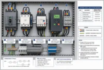
An industrial control panel interior with a 65 kA breaker, a contactor, overload relay, VFD and distribution block (5 to 10 kA short-circuit ratings), with the lowest SCCR of 5 kA limiting the panel. A reference table and definitions are included.

Fault Current Decay Along a 10,000 ft Feeder (thumbnail)🔒 All-Access

Fault Current Decay Along a 10,000 ft Feeder

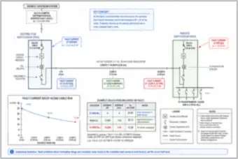
A 34.5 kV feeder from a distribution switchgear at 25.00 kA to a remote switchgear 10,000 ft away, where the available fault current falls to 16.74 kA at the midpoint and 12.58 kA at the end, with a decay curve and the calculation.

Campus One-Line and Per-Unit Impedance Diagram on a 100 MVA Base (thumbnail)🔒 All-Access

Campus One-Line and Per-Unit Impedance Diagram on a 100 MVA Base

A 115 kV utility to 34.5 kV campus bus with 22 MVA gas turbine generators, two 75 MVA data center paths and a station service system, with the matching per-unit impedance diagram and the conversion of each transformer and generator impedance to the 100 MVA base.

Per-Unit System: Base MVA, Base kV, Base Current and Base Impedance (thumbnail)🔒 All-Access

Per-Unit System: Base MVA, Base kV, Base Current and Base Impedance

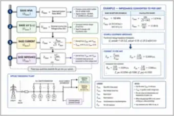
A four-step walk through the per-unit system (base MVA, base kV, base current Ibase = Sbase ÷ (√3 Vbase), base impedance Zbase = Vbase² ÷ Sbase), with a worked example converting a 1.25 Ω transformer impedance to 0.1050 per unit on a 100 MVA, 34.5 kV base.

Transformer and Generator Nameplates Compared on a Common 10 MVA Base (thumbnail)🔒 All-Access

Transformer and Generator Nameplates Compared on a Common 10 MVA Base

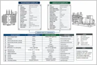
A 2 MVA, 6.0% transformer nameplate and a 5 MVA, 0.15 pu X″d generator nameplate converted to a common 10 MVA base (0.30 per unit each), with a side-by-side parameter comparison and notes on subtransient reactance.

Per-Unit Fault Calculation at a 4.16 kV Bus: 14.61 kA (thumbnail)🔒 All-Access

Per-Unit Fault Calculation at a 4.16 kV Bus: 14.61 kA

A 500 MVA utility source (0.02 pu) and a 10 MVA, 7.5% transformer on a 10 MVA base give a total of j0.095 pu, a 1,388 A base current and a 14.61 kA three-phase bolted fault at the 4.16 kV bus, shown with the equivalent circuit.

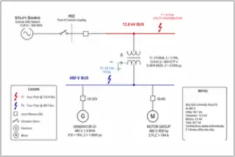
Fault Current at a 480 V Bus: Utility, Generator and Motor Contributions (thumbnail)🔒 All-Access

Fault Current at a 480 V Bus: Utility, Generator and Motor Contributions

A 13.8 kV, 500 MVA utility feeding a 2.5 MVA transformer to a 480 V bus with a 1.5 MVA generator and a 600 hp motor group. The utility supplies 48.1 kA, the generator 12.0 kA and motors 3.0 kA, for 63.1 kA total.

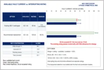
Available Fault Current vs. Interrupting Rating: 65 kA and 100 kA Switchgear (thumbnail)🔒 All-Access

Available Fault Current vs. Interrupting Rating: 65 kA and 100 kA Switchgear

A comparison of 63.1 kA available fault current against 65 kA existing switchgear (a 3.0% margin) and 100 kA replacement switchgear (58.5%), with the utility, generator and motor contributions and a note that interrupting duty and short-time withstand are separate ratings.

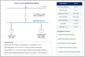
Study Summary: Fault Results, Switchgear Margin and Recommended Changes (thumbnail)🔒 All-Access

Study Summary: Fault Results, Switchgear Margin and Recommended Changes

A one-page summary of a 13.8 kV utility, 2.5 MVA transformer, generator and motor system: 20.9 kA at the 13.8 kV bus and 63.1 kA at the 480 V bus, a 3.0% margin on 65 kA gear against 58.5% on 100 kA, 14.2 to 3.8 cal/cm² with ZSI, a 5 A (55.4 Ω) HRG option and five recommended changes.

Protection, Coordination & Arc Flash

Time-current curves, fuses, selectivity, incident energy, boundaries and arc protection
11 drawings
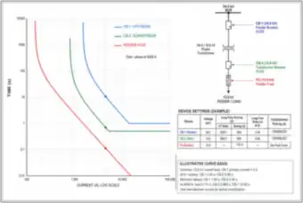
Time-Current Curves: Two Breakers and a Fuse at 34.5 kV and 13.8 kV (thumbnail)🔒 All-Access

Time-Current Curves: Two Breakers and a Fuse at 34.5 kV and 13.8 kV

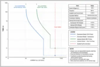
A log-log time-current plot for an upstream feeder breaker, a transformer breaker and a feeder fuse, with their long-time pickup and delay settings, their relative clearing times at 4500 A, and the one-line they protect.

Selective Coordination: 100 A Downstream and 400 A Upstream Breakers (thumbnail)🔒 All-Access

Selective Coordination: 100 A Downstream and 400 A Upstream Breakers

A time-current plot for a 100 A and a 400 A breaker at a 4,500 A fault on a 480 V system. The downstream breaker clears in 0.016 s and the upstream in 0.100 s, a 0.084 s margin, with the study values listed.

Two Current-Limiting Fuses in Series: Selectivity Ratio (thumbnail)🔒 All-Access

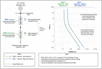
Two Current-Limiting Fuses in Series: Selectivity Ratio

A 400 A upstream and a 150 A downstream Class J fuse in series on a 480 V source, with their melting and total-clearing time-current curves, a 2.67:1 ratio exceeding the 2:1 guideline, and notes on I²t selectivity data.

Primary Fuse Curve vs. Transformer Inrush: 1,000 kVA at 12.47 kV (thumbnail)🔒 All-Access

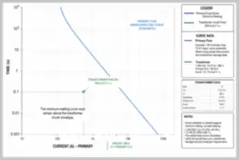
Primary Fuse Curve vs. Transformer Inrush: 1,000 kVA at 12.47 kV

A schematic minimum-melting curve for a 100 A, 15 kV class primary fuse against the 556 A, 0.1 s inrush point of a 1,000 kVA transformer (12 × the 46.30 A primary full-load current), with the transformer data and notes.

Arc Flash in a 480 V Switchgear Cell: Boundary, Incident Energy and PPE (thumbnail)🔒 All-Access

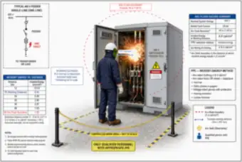
Arc Flash in a 480 V Switchgear Cell: Boundary, Incident Energy and PPE

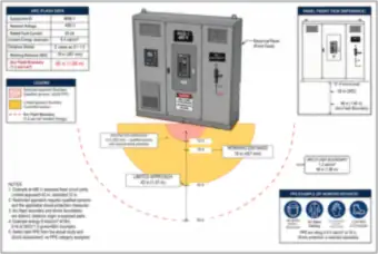
An arc fault in a 480 V feeder cell with a 66 in. arc-flash boundary, 8.4 cal/cm² incident energy at an 18 in. working distance, a table of incident energy against distance, PPE for the incident-energy method and a controlled work area.

Arc-Flash, Limited Approach and Restricted Approach Boundaries at a Panel (thumbnail)🔒 All-Access

Arc-Flash, Limited Approach and Restricted Approach Boundaries at a Panel

A 480 V switchboard with a plan view of the restricted approach (12 in.), working distance (18 in.), limited approach (42 in.) and 66 in. arc-flash boundary, with the arc-flash data for a 25 kA bolted fault and an example PPE panel.

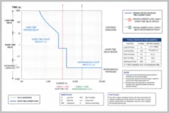
Breaker Time-Current Curve and Arcing Current: Short-Time vs. Instantaneous (thumbnail)🔒 All-Access

Breaker Time-Current Curve and Arcing Current: Short-Time vs. Instantaneous

A 400 A breaker curve with long-time, short-time (2400 A, 0.50 s) and instantaneous (4800 A) regions, with a 3,400 A low arcing current clearing in 0.50 s and an 18,000 A high arcing current clearing in 0.01 s, plus settings and how to read the chart.

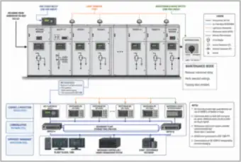
Switchgear Lineup with Arc-Flash Relay, Light Sensors and Maintenance Mode Switch (thumbnail)🔒 All-Access

Switchgear Lineup with Arc-Flash Relay, Light Sensors and Maintenance Mode Switch

A 34.5 kV switchgear lineup with an arc-flash relay, light sensors in each section and a key-operated maintenance-mode switch, with the control, communications and supervisory layers (IEC 61850, a redundant Ethernet ring, SCADA and a microgrid controller).

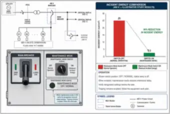
Maintenance Mode Switch on a Main Breaker: Incident Energy Reduction (thumbnail)🔒 All-Access

Maintenance Mode Switch on a Main Breaker: Incident Energy Reduction

A 480 V main breaker with a maintenance-mode switch and status lamp, and a chart where switching to maintenance mode cuts illustrative incident energy from 25 cal/cm² to 2.5 cal/cm², a 90% reduction, with the operating notes.

Optical Arc Protection in Switchgear: Sensors, Relay and Clearing Timeline (thumbnail)🔒 All-Access

Optical Arc Protection in Switchgear: Sensors, Relay and Clearing Timeline

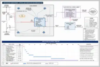
A switchgear compartment with optical arc sensors, an arc protection relay hard-wired to the upstream breaker trip coil, and a plant control cabinet with SCADA, plus a clearing timeline of nine steps from arc initiation to event logging over about 200 ms.

Time-Current Coordination and Arc-Flash Study Summary: ZSI Reduces 14.2 to 3.8 cal/cm² (thumbnail)🔒 All-Access

Time-Current Coordination and Arc-Flash Study Summary: ZSI Reduces 14.2 to 3.8 cal/cm²

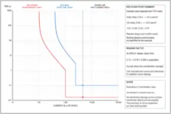
A time-current plot for a 100 A feeder and a 400 A main at 4500 A (0.084 s separation) with an arc-flash summary where zone-selective interlocking cuts the delay from 0.30 s to 0.08 s, lowering incident energy from 14.2 to about 3.8 cal/cm², plus notes on reading the plot.

Grounding & Bonding

Grid and rods, resistance and high-resistance grounding, equipment grounding and ground-fault paths
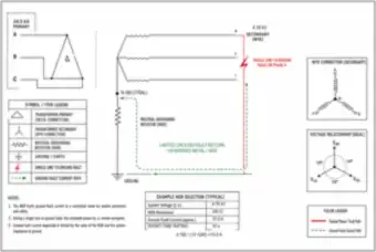
8 drawings
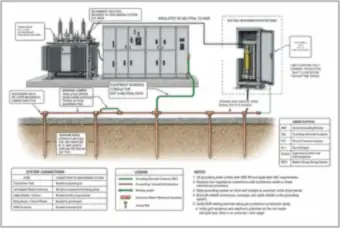
Resistance-Grounded Transformer: Neutral Grounding Resistor and Ground Grid (thumbnail)🔒 All-Access

Resistance-Grounded Transformer: Neutral Grounding Resistor and Ground Grid

A 34.5 kV to 4.16 kV wye transformer with its neutral connected to a 240 Ω, 10 A, 10 s neutral grounding resistor, switchgear bonded to a ground grid with rods and exothermic connections, a connections table and notes.

Neutral Grounding Resistor: Single Line-to-Ground Fault Current Path (thumbnail)🔒 All-Access

Neutral Grounding Resistor: Single Line-to-Ground Fault Current Path

A delta-wye transformer with a neutral grounding resistor and a single line-to-ground fault on phase A. A 240 Ω resistor limits the ground-fault current to about 10 A (4,160 ÷ (√3 × 240)), with the return path, wye phasors and an NGR selection table.

Two Ground Rods at 6 ft Spacing: Current Flow and Overlapping Soil Regions (thumbnail)🔒 All-Access

Two Ground Rods at 6 ft Spacing: Current Flow and Overlapping Soil Regions

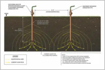
Two 5/8 in. × 10 ft copper-clad ground rods 6 ft apart, with current flow paths and equipotential lines showing the overlapping soil regions, and notes on why their resistances do not combine as two independent resistors.

Feeder with Enlarged Phase Conductors and an Upsized Equipment Grounding Conductor (thumbnail)🔒 All-Access

Feeder with Enlarged Phase Conductors and an Upsized Equipment Grounding Conductor

A 480 V feeder in rigid metal conduit with phase conductors increased from 3 AWG to 1/0 AWG and an equipment grounding conductor upsized from 8 AWG to 4 AWG, with a cross-section detail, a conductor schedule and sizing notes.

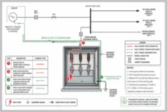
Ground-Fault Current Path from a Faulted Phase to the Source (thumbnail)🔒 All-Access

Ground-Fault Current Path from a Faulted Phase to the Source

A ground fault inside a switchgear enclosure shown step by step, with fault current flowing from the phase conductor to the enclosure, through the equipment grounding conductor and back through the source neutral bond. A 0.0285 Ω loop gives about 9,719 A.

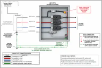
Phase-to-Enclosure Fault in a 480Y/277 V Panel: Return Path via the EGC (thumbnail)🔒 All-Access

Phase-to-Enclosure Fault in a 480Y/277 V Panel: Return Path via the EGC

A phase conductor touching the metal enclosure of a 480Y/277 V distribution panel, with the fault current returning through the equipment grounding conductor and the transformer neutral bond, not through earth alone, and notes on the isolated downstream neutral.

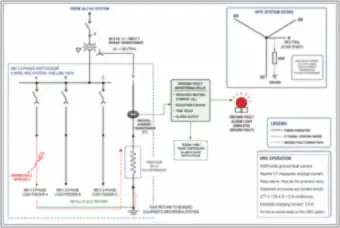
High-Resistance Grounding: 5 A NGR, Neutral CT and Ground-Fault Alarm (thumbnail)🔒 All-Access

High-Resistance Grounding: 5 A NGR, Neutral CT and Ground-Fault Alarm

A 480 V high-resistance grounded system on a 34.5 kV delta to 480 V wye transformer, with a 55.4 Ω neutral grounding resistor limiting a ground fault to 5 A (277 ÷ 55.4), a neutral CT, a monitoring relay, alarm light and SCADA signals.

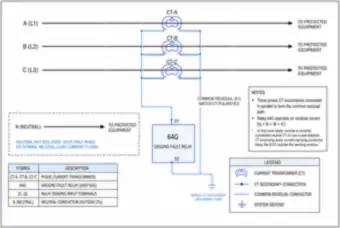
Residual Ground-Fault Relay: Three Phase CTs in Parallel (64G) (thumbnail)🔒 All-Access

Residual Ground-Fault Relay: Three Phase CTs in Parallel (64G)

Three phase current transformers with their secondaries connected in parallel to a 64G ground-fault relay, forming a common residual path, with notes on four-wire loads, polarity matching and keeping the equipment ground outside the CT window.

Power Factor, Harmonics & Power Quality

Capacitor banks, resonance, harmonics and filters, sags, swells and voltage unbalance
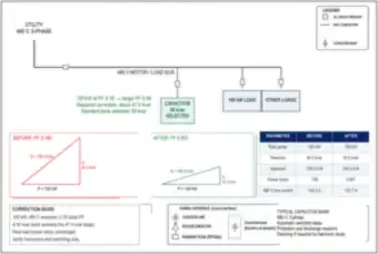
16 drawings
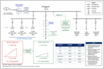
Power Factor Correction: 100 kW Load from 0.78 to 0.95 (thumbnail)🔒 All-Access

Power Factor Correction: 100 kW Load from 0.78 to 0.95

A 480 V bus with a 100 kW load at 0.78 power factor, corrected with a 50 kvar capacitor bank (about 47.4 kvar needed). Before-and-after power triangles show the power factor reaching 0.957 and the line current falling from 154.2 A to 125.7 A.

Capacitor Bank on a 480 V Motor Control Center Bus (thumbnail)🔒 All-Access

Capacitor Bank on a 480 V Motor Control Center Bus

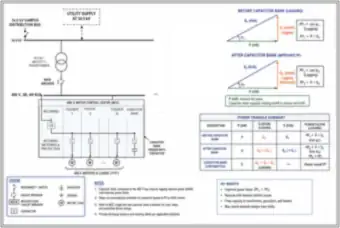
A one-line diagram from a 34.5 kV supply through a transformer to a 480 V motor control center with a contactor-switched capacitor bank feeder, shown with before-and-after power triangles, a summary table and the benefits of correction.

Utility Bill Excerpt: kVA Demand Charges Before and After PF Correction (thumbnail)🔒 All-Access

Utility Bill Excerpt: kVA Demand Charges Before and After PF Correction

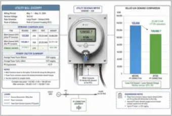
A billing excerpt beside a kVA demand meter and a bar chart. Raising the average power factor from 0.80 to 0.97 lowers billed demand from 133,000 kVA to 109,690.7 kVA, a saving of $291,366 in the month.

Distorted Current Waveform and Its Harmonic Components (thumbnail)🔒 All-Access

Distorted Current Waveform and Its Harmonic Components

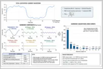
A distorted current waveform built from its 1st, 3rd, 5th, 7th, 11th and 13th harmonics, with a harmonic magnitude bar chart, a total RMS current of 1.0466 A, a THD of 30.9% and the displacement power factor of 0.951.

Distorted Current Waveform and Harmonic Spectrum: 15.17% THD (thumbnail)🔒 All-Access

Distorted Current Waveform and Harmonic Spectrum: 15.17% THD

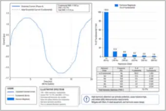
A phase A current waveform compared with an ideal sine wave, with a bar chart and table of harmonics from the 1st to the 11th (3rd at 12.5%, 5th at 6.8%) giving a total harmonic distortion of 15.17%.

Third-Harmonic Currents Adding in the Neutral of a Three-Phase Four-Wire System (thumbnail)🔒 All-Access

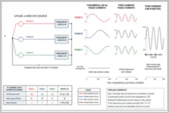
Third-Harmonic Currents Adding in the Neutral of a Three-Phase Four-Wire System

Three nonlinear loads on a wye source, with fundamental phase currents cancelling in the neutral but third-harmonic currents all in phase and adding to three times the phase value (IN3 = 3 × I3), shown with waveforms and a summary table.

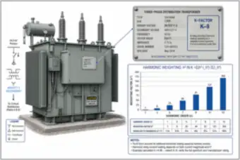
K-Rated Transformer: Nameplate and Harmonic Weighting (thumbnail)🔒 All-Access

K-Rated Transformer: Nameplate and Harmonic Weighting

A 1,500 kVA, 34.5 kV to 480Y/277 V K-9 transformer with its nameplate, a chart of harmonic weighting factors (h²) from the 1st to the 13th harmonic, and an example K-factor of 4.96 leading to selection of a K-9 rating.

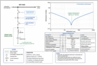
Series-Tuned Passive Harmonic Filter at 282 Hz (thumbnail)🔒 All-Access

Series-Tuned Passive Harmonic Filter at 282 Hz

A 480 V series-tuned passive filter branch with a switching contactor, CT, disconnect, 0.2767 mH reactor and 1151.3 µF capacitor, tuned to 282 Hz (4.7th harmonic), with its impedance-versus-frequency notch and a design parameters table.

Voltage Sag, Swell and Transient Waveforms (thumbnail)🔒 All-Access

Voltage Sag, Swell and Transient Waveforms

A 60 Hz voltage waveform running through nominal, sag, swell, transient and return to nominal, with the magnitude, duration and typical causes of each disturbance (faults and motor starting, load rejection and capacitor switching, lightning and switching).

Motor-Start Voltage Dip at a 480 V Bus (thumbnail)🔒 All-Access

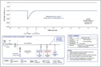
Motor-Start Voltage Dip at a 480 V Bus

A voltage-versus-time plot at a 480 V bus where a large motor start drops the voltage to 0.893 per unit (428.6 V), a 10.7% dip, recovering in about 1.0 second, with the system context one-line and an event summary.

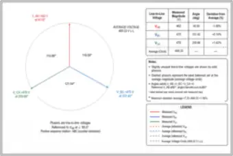
Voltage Unbalance: Three Line-to-Line Phasors (thumbnail)🔒 All-Access

Voltage Unbalance: Three Line-to-Line Phasors

A phasor diagram of slightly unequal line-to-line voltages (462 V, 470 V and 476 V) against the 469.33 V average, with their angles, each phase’s deviation from the average and a maximum deviation of 1.56%.

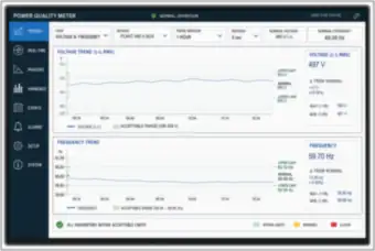
Power Quality Meter Screen: Voltage and Frequency Trends (thumbnail)🔒 All-Access

Power Quality Meter Screen: Voltage and Frequency Trends

A power quality meter display for a plant 480 V bus showing one-hour voltage (497 V, +3.54% from nominal) and frequency (59.70 Hz) trends against acceptable ranges, with menu tabs for phasors, harmonics, events and alarms.

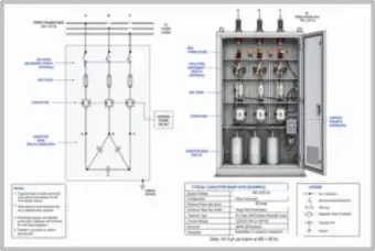
Capacitor Bank Cabinet: Delta-Connected, Fused and Contactor-Switched (thumbnail)🔒 All-Access

Capacitor Bank Cabinet: Delta-Connected, Fused and Contactor-Switched

A 50 kvar, 480 V delta-connected capacitor bank cabinet with HRC fuses, a capacitor-duty contactor, an optional isolating switch and control power, shown as a one-line and a cabinet view, with typical bank data and notes.

Delta and Wye Capacitor Banks Compared: 50 kvar at 480 V (thumbnail)🔒 All-Access

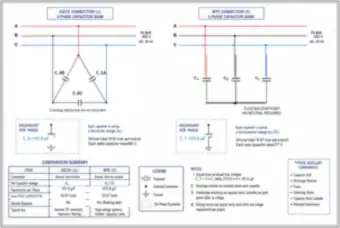
Delta and Wye Capacitor Banks Compared: 50 kvar at 480 V

The same 50 kvar, 480 V capacitor bank connected in delta (191.9 µF per phase, 480 V across each unit) and in wye (575.6 µF, 277 V across each unit), each with its per-phase equivalent and a comparison summary table.

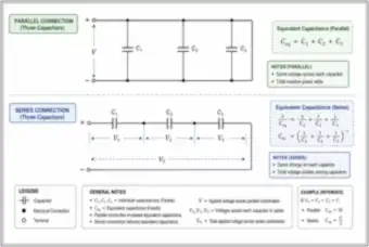
Capacitors in Parallel and in Series: Equivalent Capacitance (thumbnail)🔒 All-Access

Capacitors in Parallel and in Series: Equivalent Capacitance

Three capacitors connected in parallel (Ceq = C1 + C2 + C3) and in series (the reciprocals add), with the voltage and charge relationships for each and the equal-value example of 3C in parallel and C/3 in series.

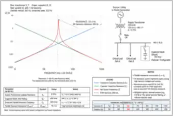
Parallel Resonance: Capacitor Bank and Supply Transformer at 323 Hz (thumbnail)🔒 All-Access

Parallel Resonance: Capacitor Bank and Supply Transformer at 323 Hz

A 600 kvar capacitor bank on a 480 V bus fed by a 1000 kVA, 5.75% impedance transformer. The reactance plots cross near 323 Hz, close to the 5th harmonic (300 Hz), producing an impedance peak of about 5.1 Ω, with mitigation options listed.

Lighting

Mounting height, ceiling plans, warehouse and parking-lot lighting, and emergency lighting
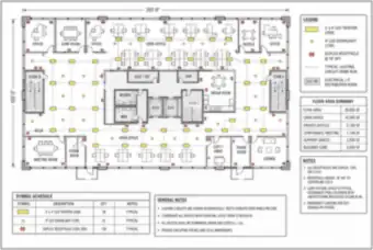
6 drawings
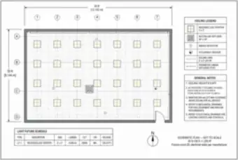
Office Floor Plan: Lighting and Receptacle Layout, 20,000 sq ft (thumbnail)🔒 All-Access

Office Floor Plan: Lighting and Receptacle Layout, 20,000 sq ft

A 200 ft × 100 ft office floor plan showing 58 LED troffers, 42 downlights and 128 duplex receptacles, with the floor area summary, a symbol schedule and general notes.

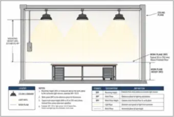
Luminaire Mounting Height and Work Plane: Section View (thumbnail)🔒 All-Access

Luminaire Mounting Height and Work Plane: Section View

A building section with ceiling-mounted high-bay luminaires 22 ft above a 30 in. work plane (24.5 ft above the floor), with the light rays, definitions of mounting height, work plane and work plane height, and notes.

Reflected Ceiling Plan: 40 × 30 ft Office with 28 LED Troffers (thumbnail)🔒 All-Access

Reflected Ceiling Plan: 40 × 30 ft Office with 28 LED Troffers

A reflected ceiling plan of a 1,200 sq ft office with 28 recessed 2×2 LED troffers (4,000 lm, 3500 K) in 7 columns and 4 rows, a return air diffuser, smoke detectors and an occupancy sensor, with a fixture schedule and notes.

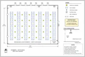
Warehouse Floor Plan: High-Bay Lighting over Racking Aisles (thumbnail)🔒 All-Access

Warehouse Floor Plan: High-Bay Lighting over Racking Aisles

A 200 × 100 ft warehouse with seven pallet racks and 30 high-bay LED luminaires (6 aisles of 5, 21,000 lm each) mounted 22 ft above the work plane, with dock doors, an electrical room, a legend and a luminaire section.

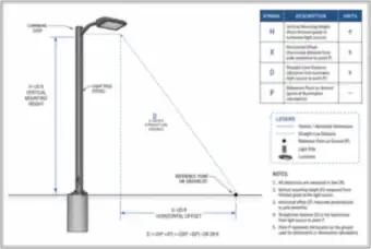
Parking-Lot Light Pole: Mounting Height, Offset and Straight-Line Distance (thumbnail)🔒 All-Access

Parking-Lot Light Pole: Mounting Height, Offset and Straight-Line Distance

A pole-mounted LED luminaire with a 20 ft mounting height and a 20 ft horizontal offset to a ground reference point, giving a 28.28 ft straight-line distance (D = √(H² + X²)) used in illumination calculations.

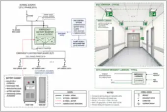
Emergency Lighting: Battery Inverter, Panelboard and Exit Corridor (thumbnail)🔒 All-Access

Emergency Lighting: Battery Inverter, Panelboard and Exit Corridor

A centrally supplied emergency lighting system with a battery inverter, automatic transfer, an emergency lighting panelboard and a battery cabinet, serving exit corridor luminaires, with a 24 V battery sizing example (18.75 Ah, 23.44 Ah with aging, select 25 Ah or more).

Solar PV & EV Charging

PV arrays and string voltage, solar production, and Level 1, Level 2 and DC fast charging
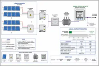
11 drawings
2 MW Solar Array: Single-Line Diagram and Annual Energy Production (thumbnail)🔒 All-Access

2 MW Solar Array: Single-Line Diagram and Annual Energy Production

A 2 MW solar plant from PV strings, combiner boxes and inverters through 480 V switchgear and a 0.48/34.5 kV step-up transformer to a revenue meter, with 2,314,587 kWh produced in the year, a 13.2% capacity factor.

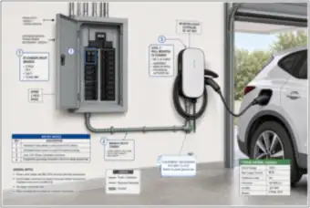
Garage Level 2 EV Charger: Breaker, Conduit and Grounding (thumbnail)🔒 All-Access

Garage Level 2 EV Charger: Breaker, Conduit and Grounding

A wall-mounted 240 V, 40 A Level 2 charger on a dedicated 50 A two-pole breaker, fed with #6 AWG copper in 3/4 in. EMT with a #10 AWG equipment ground, with keyed notes and typical ratings.

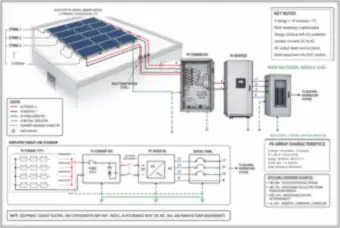
Rooftop PV Array: Strings, Combiner Box, Inverter and Service Panel (thumbnail)🔒 All-Access

Rooftop PV Array: Strings, Combiner Box, Inverter and Service Panel

A rooftop array of 4 strings of 18 modules (72 modules, 39.31 kW DC) wired to a combiner box with fuses and surge protection, a 30 kW inverter and a service panel, with a single-line, array characteristics and applicable standards.

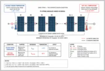
PV String Voltage: Cold-Temperature Voc and Hot-Cell Vmp (thumbnail)🔒 All-Access

PV String Voltage: Cold-Temperature Voc and Hot-Cell Vmp

A string of 18 modules checked at two design conditions: the coldest temperature (−10°C) gives a maximum of about 975 V, under the 1000 V limit, and a 65°C hot cell gives a minimum operating voltage of about 649 V for the inverter MPPT window.

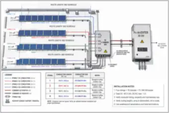
Rooftop PV Array: String Routing, Conductor Lengths and Combiner (thumbnail)🔒 All-Access

Rooftop PV Array: String Routing, Conductor Lengths and Combiner

A rooftop with four 18-module strings routed in #10 AWG PV wire (150 to 165 ft) to a combiner box and a 30 kW inverter with a 480 V, three-phase output, with a conductor length schedule and installation notes.

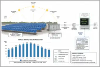
2.4 MW DC / 2.0 MW AC Solar Array: Interconnection and Monthly Production (thumbnail)🔒 All-Access

2.4 MW DC / 2.0 MW AC Solar Array: Interconnection and Monthly Production

A fixed-tilt 2.4 MW DC, 2.0 MW AC array feeding a 690 V to 34.5 kV step-up transformer and revenue meter, with a daily sun path, monthly production bars (240 to 471 MWh) and 4,380 MWh a year at a 25.0% capacity factor.

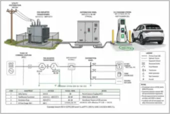
EV Fast Charger Supply: 34.5 kV Transformer to 480 V Distribution Panel (thumbnail)🔒 All-Access

EV Fast Charger Supply: 34.5 kV Transformer to 480 V Distribution Panel

A utility pad-mounted transformer, 480Y/277 V distribution panel and a 150 kW DC fast charger, with a one-line, grounding system and equipment table, and an example 250 A branch with 250 kcmil copper (255 A) for a 193.8 A load.

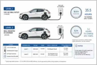
EV Charging Levels: Level 1 vs. Level 2 Time to Charge 20% to 80% (thumbnail)🔒 All-Access

EV Charging Levels: Level 1 vs. Level 2 Time to Charge 20% to 80%

A 1.44 kW Level 1 outlet charge takes 35.5 hours and a 9.6 kW Level 2 wall charger 5.2 hours, for a 75 kWh battery from 20% to 80%, with the circuit, protection and typical range added per hour for each level.

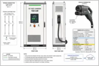
150 kW DC Fast Charger: Cabinet, Connector and Nameplate (thumbnail)🔒 All-Access

150 kW DC Fast Charger: Cabinet, Connector and Nameplate

Front and side views of a 150 kW DC fast charger (900 × 600 × 2000 mm) with its CCS1 connector, a nameplate showing 150 to 1000 VDC output and 193.8 A full-load input at 480 V, the AC power connection and installation notes.

Twelve Level 2 Charging Posts with an Energy-Management Controller (thumbnail)🔒 All-Access

Twelve Level 2 Charging Posts with an Energy-Management Controller

A row of twelve 208 V Level 2 posts on one panel with an energy-management controller and current transducer limiting total current to an 80 kVA, 222 A setpoint, sharing it equally or by priority, with OCPP and Modbus communication to a supervisory system.

Delivery Van Depot: Twenty Level 2 Chargers on a Single-Phase Distribution (thumbnail)🔒 All-Access

Delivery Van Depot: Twenty Level 2 Chargers on a Single-Phase Distribution

A depot with twenty vans on 40 A, 2-pole Level 2 chargers and an overnight 10-hour charging window. Twenty chargers at 7.68 kW give 153.6 kW, 192 kVA continuous, fed through two transformers and an 800 A panel.

Data Centers

2N power paths, racks, busways, UPS systems, PUE and utility-to-rack design
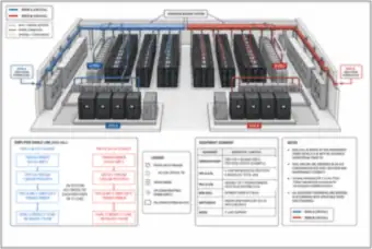
8 drawings
Data Hall with A and B Power Paths: Overhead Busway, UPS and PDUs (thumbnail)🔒 All-Access

Data Hall with A and B Power Paths: Overhead Busway, UPS and PDUs

A 2N data hall where two independent paths (A and B, each 4 × 400 kW UPS and a 34.5 kV to 480 V transformer) feed row PDUs and overhead 208Y/120 V busway to 160 dual-corded racks of 10 kW, with no automatic cross-tie.

Server Rack with Dual PDUs: 2N Power Paths A and B (thumbnail)🔒 All-Access

Server Rack with Dual PDUs: 2N Power Paths A and B

A server rack with two vertical PDUs on independent 208Y/120 V paths. An 8 kW rack load draws 23.4 A per PDU at 208 V, three-phase, 0.95 power factor on a 30 A breaker, and either PDU must carry the full load if the other path is lost.

Data Center Facility Load Breakdown and PUE of 1.383 (thumbnail)🔒 All-Access

Data Center Facility Load Breakdown and PUE of 1.383

A stacked bar of a 1,660 kW facility: 1,200 kW IT load (72.29%), 360 kW cooling, 50 kW UPS losses, 30 kW distribution losses and 20 kW miscellaneous, giving a power usage effectiveness of 1,660 ÷ 1,200 = 1.383.

Overhead Busway Feeding a Row of Server Racks (thumbnail)🔒 All-Access

Overhead Busway Feeding a Row of Server Racks

A 600 A, 208Y/120 V overhead busway from a distribution panel with plug-in units and flexible cables feeding each rack PDU, with a plug-in unit detail showing 23.4 A, 8.0 kW and 0.95 power factor, and key notes on shutters and interlocks.

Data Hall Layout: Five Rows of 16 Racks on A and B 208 V Row Busways (thumbnail)🔒 All-Access

Data Hall Layout: Five Rows of 16 Racks on A and B 208 V Row Busways

An 80-rack, 800 kW data hall with five rows of 16 racks, each row fed by 600 A, 208 V busways from independent A and B PDUs and remote power panels, with a hall basis table and the row busway sizing (467.5 A × 125% = 584.4 A, select 600 A).

Two Independent UPS Systems: A and B Each 4 × 400 kW with Battery (thumbnail)🔒 All-Access

Two Independent UPS Systems: A and B Each 4 × 400 kW with Battery

Two independent UPS systems, each four 400 kW modules (1,600 kW) with a rectifier, inverter, static bypass and its own battery string, feeding separate 480 V distribution to dual-corded loads. Battery sizing is 10 minutes at 95% efficiency with a 1.25 aging factor, 351 kWh or more.

Utility-to-Rack One-Line: 34.5 kV Service, 2N UPS and Generator Plant (thumbnail)🔒 All-Access

Utility-to-Rack One-Line: 34.5 kV Service, 2N UPS and Generator Plant

A one-line from a 34.5 kV utility and four 1,000 kW generators (N+1) through two 2,500 kVA transformers, UPS A and B, PDU transformers and 600 A row busways to the racks, with design basis values, operating notes and a supervisory control layer.

Data Center Design Summary Dashboard: Power Path, UPS and PUE (thumbnail)🔒 All-Access

Data Center Design Summary Dashboard: Power Path, UPS and PUE

A summary of a 1,600 kW dual-corded data center on a 34.5 kV utility with two 2,500 kVA transformers, 2 × (4 × 400 kW) UPS, 2,216.7 kW facility power (PUE 1.385), 2,333 kVA utility demand and a 52.3 kA transformer-only fault, in a flow and design table.

Medium-Voltage Cable & Substations

Shielded cable, duct banks, charging current, substation one-lines and bus ties
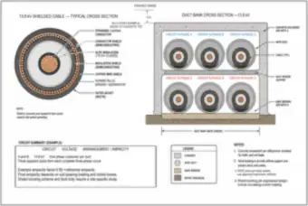
8 drawings
13.8 kV Shielded Cable Cross-Section and Concrete Duct Bank (thumbnail)🔒 All-Access

13.8 kV Shielded Cable Cross-Section and Concrete Duct Bank

A 15 kV class shielded cable (copper conductor, semiconducting shields, XLPE insulation, copper wire shield and jacket) beside a six-duct concrete-encased bank carrying two three-phase circuits at 36 in. cover, with a circuit summary and notes.

Six-Way Duct Bank at 13.8 kV: Cover, Encasement and Selected Circuit (thumbnail)🔒 All-Access

Six-Way Duct Bank at 13.8 kV: Cover, Encasement and Selected Circuit

A cross-section of a 36 in. by 48 in. concrete-encased six-duct bank 36 in. below grade with warning tape, spacers and sand bedding, highlighting circuit A2 at 5 MVA, 13.8 kV and 209.2 A per phase, with a one-line and notes.

Cable Charging Current on an 8,000 ft, 13.8 kV Underground Circuit (thumbnail)🔒 All-Access

Cable Charging Current on an 8,000 ft, 13.8 kV Underground Circuit

An 8,000 ft 13.8 kV underground cable with capacitive charging current flowing between conductor and shield, a distributed capacitance model, and the calculation C = 2.16 µF per phase and Ic = 2π × 60 × 2.16 µF × (13,800 ÷ √3) = 6.49 A per phase.

500 kcmil XLPE Cable: Construction and Allowable Fault Current (thumbnail)🔒 All-Access

500 kcmil XLPE Cable: Construction and Allowable Fault Current

A cutaway of a 15 kV class 500 kcmil copper XLPE cable with its conductor, insulation, copper tape shield and jacket, and a thermal limit curve showing 50.9 kA for 0.5 s and 20.0 kA for 3.24 s, with construction data and notes.

69 kV to 13.8 kV Substation: One-Line with Critical Paths A and B (thumbnail)🔒 All-Access

69 kV to 13.8 kV Substation: One-Line with Critical Paths A and B

A 69 kV utility incoming line with a vacuum breaker feeding a 12 MVA, 8% impedance transformer and a 13.8 kV, 1,200 A main bus, with feeder breakers to data center paths A and B and a station service feeder, optional BESS and black-start generator.

Single Transformer Substation: 69 kV Main Breaker, 12 MVA Transformer and Four Feeders (thumbnail)🔒 All-Access

Single Transformer Substation: 69 kV Main Breaker, 12 MVA Transformer and Four Feeders

A single-line diagram of a 69 kV disconnect and main breaker, a 12 MVA, 8% impedance delta-wye transformer with HV and LV CTs for 87T differential protection, a 13.8 kV main breaker and bus, and four outgoing feeders with a 502 A full load.

Substation Bus Fault Current: 5.71 kA at 13.8 kV (thumbnail)🔒 All-Access

Substation Bus Fault Current: 5.71 kA at 13.8 kV

A 69 kV utility source (1,500 MVA fault level) feeding a 12 MVA, 8% transformer and a 13.8 kV bus. The utility at 0.008 pu plus the transformer at 0.08 pu give a bus fault of 12 MVA ÷ (√3 × 13.8 kV × 0.088) = 5.71 kA.

Two-Transformer Substation with a Normally Open Bus Tie (thumbnail)🔒 All-Access

Two-Transformer Substation with a Normally Open Bus Tie

A 69 kV outdoor switchgear with two 12 MVA transformers (N−1 duty, 9.5 MVA peak giving 79.2% loading), a normally open high-voltage tie and 13.8 kV tie, a station service transformer to a 480Y/277 V bus, and an equipment count.

Industrial Plants & Energy Efficiency

Plant one-lines and equipment and lighting upgrades with their savings and payback
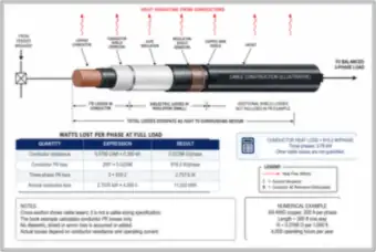
8 drawings
Cable I²R Heat Loss: 3/0 AWG, 200 A, 300 ft (thumbnail)🔒 All-Access

Cable I²R Heat Loss: 3/0 AWG, 200 A, 300 ft

A cutaway of a medium-voltage cable showing where losses occur. A 3/0 AWG copper conductor at 200 A and 300 ft has 0.02298 Ω per phase, 919.2 W per phase and 2.76 kW for three phases, or 11,030 kWh over 4,000 operating hours.

Generator Replacement: Old vs. New Efficiency, Emissions and Payback (thumbnail)🔒 All-Access

Generator Replacement: Old vs. New Efficiency, Emissions and Payback

A side-by-side of an old gas engine generator (10,500 Btu/kWh, 32.5% efficient) and a high-efficiency lean-burn unit (8,050 Btu/kWh, 42.4%), with emissions and O&M comparisons, $740,000 a year in savings and a payback of 0.88 years.

Transformer Replacement: Existing vs. High-Efficiency 75 MVA Losses (thumbnail)🔒 All-Access

Transformer Replacement: Existing vs. High-Efficiency 75 MVA Losses

Nameplates for a 2008 and a 2024 75 MVA, 34.5/13.8 kV transformer, comparing total loss at 75 MVA (549 kW vs. 308 kW) with loss bars and annual savings of 933.8 MWh, about $74,705 a year at 40% loading.

Warehouse Lighting Upgrade: Fluorescent to LED, 69% Savings (thumbnail)🔒 All-Access

Warehouse Lighting Upgrade: Fluorescent to LED, 69% Savings

A warehouse split between 500 four-lamp T8 fixtures (128 W, 256,000 kWh a year, $30,720) and 500 LED fixtures (40 W, 80,000 kWh, $9,600), saving $21,120 a year and about 93 metric tons of CO₂e, with a system comparison table.

Cash-Flow Chart: $120 Million Investment and 5.77-Year Break-Even (thumbnail)🔒 All-Access

Cash-Flow Chart: $120 Million Investment and 5.77-Year Break-Even

A bar and line chart of a $120 million on-site generation plant with annual savings growing from $16 million to $34 million, a cumulative break-even at 5.77 years and $130 million of cumulative cash flow by year 10, with a summary table.

Industrial Plant One-Line: 13.8 kV Utility, Main Switchgear, MCC and Standby Generator (thumbnail)🔒 All-Access

Industrial Plant One-Line: 13.8 kV Utility, Main Switchgear, MCC and Standby Generator

A 13.8 kV utility feeding a 1,000 kVA transformer, 1000 A main switchgear and a motor control center, with a 300 kW standby generator and transfer switch for a critical load bus (225.8 kVA, pump-start dip of about 11.7%).

Plant Main Bus with Capacitor Bank: Power Factor Raised from 0.820 to 0.954 (thumbnail)🔒 All-Access

Plant Main Bus with Capacitor Bank: Power Factor Raised from 0.820 to 0.954

A 480 V plant main bus with motor loads and a 200 kvar capacitor bank in four 50 kvar steps under automatic power factor control. Reactive power drops from 364.0 to 164.0 kvar, kVA from 636.0 to 546.7 and I²R loss to 73.9%.

Industrial Plant One-Line with Fault Current at Each Location (thumbnail)🔒 All-Access

Industrial Plant One-Line with Fault Current at Each Location

A 13.8 kV, 500 MVA utility feeding a 1,000 kVA transformer to 480 V switchgear and an MCC, with fault currents of 20.2 kA at the transformer secondary, 20.1 kA at the switchgear and 19.1 kA at the MCC plus about 1.7 kA from motors, and a grounding electrode system.

Industrial Facilities & Cyber Risk

What an industrial facility looks like, how IT and OT priorities differ, and how a cyber event can become a physical consequence
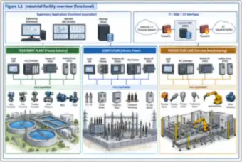
4 drawings
Industrial facility overview (thumbnail)🔒 All-Access

Industrial facility overview

A functional overview of an industrial facility with supervisory applications (engineering workstation, SCADA HMI, historian) and IT, industrial DMZ and OT interfaces behind two firewalls, above three examples: a treatment plant, an electric substation and a discrete manufacturing line, each with HMI, PLC, remote I/O, drives and field equipment.

IT versus OT priorities (thumbnail)🔒 All-Access

IT versus OT priorities

IT and OT environments side by side: an office network of workstations, laptops, email, application servers and cloud services, and a plant network of SCADA, HMI, engineering workstation, historian, two PLCs and field devices, each with its own priority order (confidentiality first for IT, safety and availability first for OT).

Cyber consequence chain (thumbnail)🔒 All-Access

Cyber consequence chain

A six-column chain from a single cyber event (malware, unauthorized access, denial of service, data manipulation) through loss of plant systems and loss of view or control to equipment damage, unsafe conditions, service interruption, environmental release and community impact, with safety systems and operator intervention shown as points where escalation can be stopped.

Lifecycle ribbon (thumbnail)🔒 All-Access

Lifecycle ribbon

A ribbon of eight lifecycle phases from design, procurement, construction and commissioning through operation, maintenance, modification and decommissioning, each tied to the security artifact it produces (zone drawing, security specification, as-built network drawing, hardening record, monitoring dashboard, patch log, change record and sanitization certificate).

Control Systems & Safety

Transmitter loops, PLC racks and scan cycles, HMIs, wide-area SCADA, DCS and safety instrumented systems
9 drawings
Plant architecture (thumbnail)🔒 All-Access

Plant architecture

The Purdue-style levels of a plant, from Level 0 physical process (pressure transmitter, control valve, motor starter) up through Level 1 PLC and remote I/O, Level 2 HMI, Level 3 site operations and Level 3.5 industrial DMZ to Level 4 enterprise and Level 5 cloud, with Firewall A and B and an industrial Ethernet ring of managed switches.

Pressure-transmitter signal path (thumbnail)🔒 All-Access

Pressure-transmitter signal path

A seven-step signal path for a steam header pressure measurement, from the process and a HART smart transmitter through a powered 4–20 mA loop, a PLC analog input and control logic to an HMI and the final control valve, with five labeled digital access points (transmitter configuration, PLC programming port, HMI tag write, historian and controller network interface).

PLC rack architecture (thumbnail)🔒 All-Access

PLC rack architecture

A PLC rack showing the power supply, CPU (key switch and programming port), 32-point digital input and output modules, analog input and output modules and an Ethernet communication module, with field wiring colors to sensors, solenoids, transmitters and control valves, and a remote I/O drop linked over Ethernet.

PLC scan cycle (thumbnail)🔒 All-Access

PLC scan cycle

The four-step PLC scan cycle (input scan 2.5 ms, program execution 3.0 ms, output update 3.0 ms, communications window 1.5 ms, 10 ms total) drawn as a ring and a timeline, with the communications window shared by HMI polling, engineering software, peer controllers and diagnostics.

Water-pump HMI (thumbnail)🔒 All-Access

Water-pump HMI

An annotated water pump station HMI screen with a user-role indicator, remote-sessions indicator, alarm banner, wet well level and pump status (N+1), level setpoints with write-enabled controls and an alarm history, each tied to a security-relevant feature such as role-based access and logged setpoint changes.

Wide-area SCADA (thumbnail)🔒 All-Access

Wide-area SCADA

A control center (SCADA servers, historian, engineering workstation, operator consoles and security servers) linked over fiber, licensed radio and cellular LTE/5G WAN paths with IPsec tunnels and site firewalls to a pump station, reservoir, treatment plant and substation, each with its own trust boundary.

DCS architecture (thumbnail)🔒 All-Access

DCS architecture

A layered distributed control system with redundant supervisory networks, independent control networks A and B, primary and standby controllers synchronized by a heartbeat, independent I/O networks and field I/O subsystems, behind a firewall to the corporate network.

Layers of protection and SIS (thumbnail)🔒 All-Access

Layers of protection and SIS

Six layers of protection around a process unit (process design, BPCS, alarms and operator response, SIS, physical mitigation, emergency response) and a safety instrumented system of sensors, logic solver and final actuators, with a one-way gateway passing read-only status to the control system.

Engineering workstation authority (thumbnail)🔒 All-Access

Engineering workstation authority

An engineering workstation as the high-value asset at the center of a hub, with the actions it performs on other systems: download logic to a PLC, change parameters on a drive, edit protective relay settings, publish HMI screens and modify the SCADA tag database, over the secure OT network under role-based access and change control.

Industrial Networking

Ethernet frames, VLANs, addressing, segmentation, inter-VLAN routing and redundancy
6 drawings
Ethernet encapsulation (thumbnail)🔒 All-Access

Ethernet encapsulation

An Ethernet frame (destination and source MAC, optional 802.1Q VLAN tag, EtherType, payload, frame check sequence) with its field sizes, and the IPv4 packet, TCP segment and application data (Modbus TCP, DNP3, IEC 61850 MMS, OPC UA) nested inside the payload, with a field description table.

VLAN access and trunk ports (thumbnail)🔒 All-Access

VLAN access and trunk ports

Three industrial switches (two access and one distribution) carrying VLAN 10 (PLC), VLAN 20 (HMI) and VLAN 30 (servers) over 802.1Q tagged trunk links, with untagged access ports for the PLC, HMI and server at each switch and a comparison of access and trunk ports.

Three-subnet addressing (thumbnail)🔒 All-Access

Three-subnet addressing

Three /24 subnets for a control network (PLC 10.20.10.0, HMI 10.20.20.0 and historian and server 10.20.30.0), each with its network, usable host and broadcast addresses and example devices, joined by a Layer-3 core switch whose SVIs act as the gateways, with an addressing summary table.

Before/after segmentation (thumbnail)🔒 All-Access

Before/after segmentation

A before-and-after comparison. On the left, every device sits on one flat VLAN 1. On the right, control cells, HMI, servers, cameras, engineering and infrastructure management each have their own VLAN behind a routed boundary with ACLs, with a table of the flows permitted between VLANs.

Inter-VLAN routing alternatives (thumbnail)🔒 All-Access

Inter-VLAN routing alternatives

Two ways to route between VLANs: a Layer-3 switch with SVIs and ACLs, or a firewall pair with each VLAN homed to it, compared on routing location, policy enforcement, protocol visibility, logging, security features and throughput.

Redundancy topologies (thumbnail)🔒 All-Access

Redundancy topologies

Three redundancy designs side by side: a six-switch ring with one STP-blocked link and RSTP recovery, dual uplinks from an access switch to two distribution switches (stacking or MLAG), and a PRP dual-LAN (A and B) design with a RedBox that sends duplicate frames for zero-time recovery from a single LAN failure.

Industrial Protocols

Modbus TCP, EtherNet/IP, OPC, BACnet, IEC 61850, MQTT and the security of each
7 drawings
Modbus TCP exchange (thumbnail)🔒 All-Access

Modbus TCP exchange

A Modbus TCP read of two holding registers between an HMI client (10.20.20.21) and a PLC server (10.20.10.11) on TCP port 502 through a controlled gateway, with the request and response frames broken down field by field in hex (transaction ID, protocol ID, length, unit ID, function code 03, addresses and register values).

EtherNet/IP (thumbnail)🔒 All-Access

EtherNet/IP

EtherNet/IP conceptual architecture: engineering workstation and HMI sending explicit messages (TCP 44818) through a managed switch to a controller that exchanges implicit cyclic I/O (UDP 2222) with remote I/O and a drive, with a port table, message type summary and a note that CIP security is optional and must be configured.

OPC Classic versus OPC UA (thumbnail)🔒 All-Access

OPC Classic versus OPC UA

OPC Classic (COM/DCOM over RPC, TCP 135 plus a server-configured dynamic port range that a firewall must restrict) compared with OPC UA (a single port, TCP 4840 by default, with SignAndEncrypt and X.509 certificate trust), showing the impacts of the first and the benefits of the second.

Building automation (thumbnail)🔒 All-Access

Building automation

A building automation system with a BACnet/IP backbone (AHU, chiller, VAV and lighting controllers) and BACnet MS/TP field networks over EIA-485, a BMS server and operator workstation, and a secured remote access path from a vendor through VPN with MFA, Firewall A, an industrial DMZ jump host and Firewall B.

Substation communications (thumbnail)🔒 All-Access

Substation communications

Substation communications in three layers: a station bus carrying GOOSE between protection IEDs, a process bus carrying sampled values from merging units attached to CTs and VTs, and a station gateway sending MMS up to the HMI and DNP3 or IEC 60870-5-104 through a firewall and the WAN to a control center.

MQTT publish/subscribe (thumbnail)🔒 All-Access

MQTT publish/subscribe

An MQTT broker in an industrial DMZ with TLS-authenticated clients (three edge sensors and a PLC gateway) publishing to and subscribing on plant topics, the historian and cloud analytics subscribing to the data, and a broker ACL table listing exactly which topics each client identity may publish or subscribe to.

Protocol/security landscape (thumbnail)🔒 All-Access

Protocol/security landscape

Industrial protocols arranged by functional band (enterprise and cloud, operations, control, field) with a table of what each offers for authentication, integrity and confidentiality and what configuration it needs, from HTTPS and OPC UA to Modbus TCP without security, PROFIBUS DP, Modbus RTU and wired HART, which have no native cryptographic protection.

Attack Paths & Incident Scenarios

Attack surfaces, IT-to-OT pivots, removable media, ransomware, Stuxnet-style spread and safety system protection
10 drawings
Attack-surface diagram (thumbnail)🔒 All-Access

Attack-surface diagram

An attack surface wheel around a protected OT system, with seven categories (people, devices, networks, software, remote access, vendors and third parties, physical access), each with representative exposures such as phishing, flat networks, unpatched vulnerabilities and unattended equipment, and an intended perimeter that the attack surface extends beyond.

Blocking an IT-to-OT pivot (thumbnail)🔒 All-Access

Blocking an IT-to-OT pivot

A before-and-after view of an IT to OT pivot. Before, a shared domain controller and file server straddle both networks on one unrestricted path. After, two firewalls and an industrial DMZ with a jump host and a read-only replicated historian allow only approved paths and block direct and pivot access from IT to OT.

Maintenance laptop quarantine (thumbnail)🔒 All-Access

Maintenance laptop quarantine

Two ways to connect a vendor laptop: plugged into a production switch, where it can reach every PLC on that switch and move laterally, versus a dedicated maintenance access port behind an OT firewall that enforces an approved work order, laptop posture check, a single target PLC, required protocols only and an approved time window.

Removable-media transfer (thumbnail)🔒 All-Access

Removable-media transfer

Moving files into a control room HMI two ways: an unsanitized path from email through a vendor drive, office PC and personal USB stick, and a controlled path through a sanitization kiosk (malware scan, file type validation, content filtering, integrity check) onto a labeled OT-only USB drive, with the OT-only media requirements.

Ransomware dependencies (thumbnail)🔒 All-Access

Ransomware dependencies

A ransomware scenario where the supervisory and management tier (domain controller, engineering workstation, historian, SCADA server, HMI station) is encrypted and isolated, and the operator loses visibility, supervisory control, trending, engineering access and remote support, while the PLCs, local HMI panels and field I/O in the control tier remain healthy.

Stuxnet conceptual propagation (thumbnail)🔒 All-Access

Stuxnet conceptual propagation

A simplified Stuxnet-style propagation chain from infected removable media to a Windows workstation, an engineering workstation, a PLC and field devices, with the control that interrupts each stage (media protection, endpoint hardening, engineering workstation controls, controller access and integrity) and a falsified-feedback path to the operator HMI.

Multi-stage intrusion timeline (thumbnail)🔒 All-Access

Multi-stage intrusion timeline

A conceptual timeline of a multi-stage distribution grid intrusion from business network access, credential collection and remote access to SCADA through breaker operations and disrupted communications, then manual restoration and full service restoration, with the defensive function that applies at each stage underneath.

IT business dependencies and OT continuity (thumbnail)🔒 All-Access

IT business dependencies and OT continuity

A pipeline during an IT outage: billing, scheduling, ERP, identity and IT services are unavailable, while local SCADA, the historian, the operations center and the pump, valve and metering station PLCs keep control of the pipeline, separated by four defined isolation points (SCADA data, historian, IT services, remote access).

Safety-system protection (thumbnail)🔒 All-Access

Safety-system protection

A safety instrumented system network with a hardened SIS engineering workstation reaching the plant OT network only through a firewall, a segregated SIS network, a safety PLC with a mode key switch and listed restrictions in run mode, voted sensor inputs, shutdown valve and motor contactor outputs, and independent protection (relief valve, annunciation).

Unsafe remote dosing changes (thumbnail)🔒 All-Access

Unsafe remote dosing changes

A hypothetical dosing-pump scenario in two parts: direct internet access to an HMI where a change from 15% to 95% is accepted with no alarm, and secured remote access through MFA, a gateway, a hardened jump host and an OT firewall where controller limits (0 to 30%, 5% per minute ramp) reject the change and raise an alarm.

Risk & Reference Architecture

Asset discovery, risk matrices, the Purdue model, flat and segmented networks and defense in depth
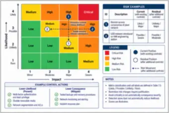
6 drawings
Asset discovery workflow (thumbnail)🔒 All-Access

Asset discovery workflow

An asset discovery workflow where drawings, site walk-downs, interviews, configuration exports and passive network capture feed one asset inventory database (ID, make, location, address, role, firmware, confidence), with a reconciliation engine that flags assets found in one source but not the others, and a review and resolve step.

Risk matrix (thumbnail)🔒 All-Access

Risk matrix

A four-by-four risk matrix of likelihood against impact with Low, Medium, High and Critical cells, two worked risk examples (remote-access compromise of the plant network and USB malware on an engineering station) moving from current to residual position after added controls, and example controls that lower likelihood or consequence.

Purdue model (thumbnail)🔒 All-Access

Purdue model

The Purdue model from Level 0 field devices up through basic control, area supervision, site operations and an industrial DMZ at Level 3.5 to enterprise and external levels 4 and 5, with typical assets, examples, approved conduits between levels and key principles for segmenting the safety system and minimizing inter-zone traffic.

Flat network (thumbnail)🔒 All-Access

Flat network

A flat network, one subnet where office PCs, operator HMIs, a historian, IP cameras, a wireless access point, PLCs and a vendor laptop can all reach one another, with only an outbound-only firewall at the internet boundary and the least-trusted devices having the same network reach as the PLCs.

Segmented facility (thumbnail)🔒 All-Access

Segmented facility

A segmented facility with an enterprise network, Firewall A, a DMZ (remote access gateway with MFA, jump host, historian replica and patch server), Firewall B and four OT zones (PLC control VLAN 10, HMI VLAN 20, site operations VLAN 30, camera and security VLAN 70), with permitted flows and notes.

Defense-in-depth rings (thumbnail)🔒 All-Access

Defense-in-depth rings

Defense in depth as seven rings around a critical process: physical, endpoint, network, application, identity, monitoring and recovery, each with its purpose and marked as a preventive, detective or recovery function, with a note that layers share dependencies and no single layer guarantees blocking an attack.

Zones & Conduits

Security zones joined by controlled conduits in manufacturing and water treatment
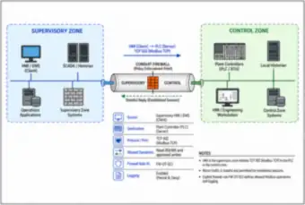
3 drawings
Two zones and a conduit (thumbnail)🔒 All-Access

Two zones and a conduit

Two security zones, supervisory and control, joined by a single conduit with a firewall at its center. A rule table shows the source (HMI), destination (PLC), protocol (Modbus TCP on port 502), allowed operations (reads and approved writes), the firewall rule ID (FW-OT-021) and logging of permits and denies.

Manufacturing zones and conduits (thumbnail)🔒 All-Access

Manufacturing zones and conduits

A manufacturing example with seven numbered conduits (C1 to C7) between zones: enterprise data to the DMZ over HTTPS, historian replication, MES to line HMIs over OPC UA, HMI to PLC with a vendor protocol, time-limited engineering access, a vendor VPN with MFA to a jump server, and a recorded RDP session to an engineering workstation.

Water-treatment zones and conduits (thumbnail)🔒 All-Access

Water-treatment zones and conduits

A water treatment network architecture in five conduits: enterprise queries to a DMZ historian replica, vendor access through a jump host, remote RTU telemetry through an encrypted WAN to an MQTT broker (TCP 8883), SCADA HMI to a treatment process PLC behind a cell firewall, and an independent safety system with hardwired shutdown and a status-only gateway.

Industrial DMZ & Historian Design

Dual-firewall and three-legged DMZs, historian replication and jump server administration
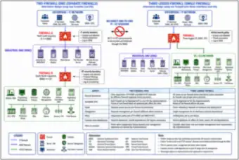
3 drawings
Dual-firewall IDMZ alternatives (thumbnail)🔒 All-Access

Dual-firewall IDMZ alternatives

Two ways to build an industrial DMZ: separate IT and OT firewalls (each with its own boundary, policy and failure domain) or a single three-legged firewall, with the DMZ services on each (jump server, historian replica, patch server, file transfer, remote access gateway) and a comparison on boundaries, availability, power, management, policy and common-mode dependencies.

Historian replication (thumbnail)🔒 All-Access

Historian replication

Historian replication through a DMZ: the OT historian initiates replication through Firewall B to a read-only replica, and enterprise dashboards, analytics and reporting tools query the replica through Firewall A, with the firewall rules and a table of component, location, role, access and direction.

Jump-server administration (thumbnail)🔒 All-Access

Jump-server administration

Jump server administration in two steps: an offsite engineer authenticates with MFA and an approved work order through a VPN gateway and IT firewall to a hardened IDMZ jump server (10.20.35.10) that logs and records the session, then an approved session from the jump server through Firewall B to a target HMI, with direct access from the engineer laptop blocked.

Firewalls

Rule matrices and firewall placement across IT, DMZ and OT
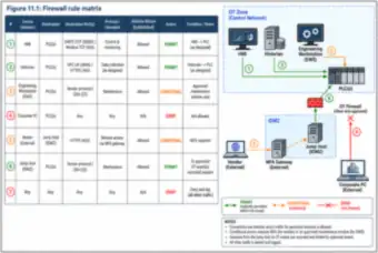
2 drawings
Firewall rule matrix (thumbnail)🔒 All-Access

Firewall rule matrix

A seven-row firewall rule matrix (HMI to PLC over DNP3 or Modbus TCP permitted, historian to PLC over OPC UA or HTTPS permitted, engineering workstation conditional on a maintenance window, corporate PC denied, vendor through an MFA gateway conditional, jump host recorded and permitted, all other traffic denied and logged) next to a zone diagram numbering each flow.

Firewall placement (thumbnail)🔒 All-Access

Firewall placement

Six numbered firewall positions in a layered network (enterprise boundary, IDMZ to OT, two control cell boundaries, a WAN boundary and a wireless support boundary) around an industrial DMZ with a historian replica, patch management, jump server and log collector, with a table naming each firewall’s purpose, security owner and approver.

Vendor & Remote Access

Poor and improved remote access, and just-in-time vendor access with break-glass
3 drawings
Poor remote access (thumbnail)🔒 All-Access

Poor remote access

Poor remote access: a vendor laptop with a shared stolen account and an unknown attacker both reach a single VPN concentrator with no user or device distinction, which opens a flat OT network of PLCs, HMIs, historian, SCADA and file servers, an engineering workstation and a printer, with the resulting risks listed.

Improved remote access (thumbnail)🔒 All-Access

Improved remote access

Improved remote access: a vendor with an MFA token goes through a TLS-encrypted VPN gateway (Firewall A), a hardened jump host with approval workflow and session recording, and an allowlist-only Firewall B to one authorized HMI, with other OT assets unreachable and a traffic policy table (RDP or HTTPS allowed from the jump host, all else denied).

Vendor access lifecycle (thumbnail)🔒 All-Access

Vendor access lifecycle

A just-in-time vendor access workflow in eight steps from a submitted request and site approval through account and firewall rule activation, MFA login, a recorded jump host session, the work, revocation at expiry and closure review, plus a five-step break-glass emergency path with sealed credentials, alerts and post-use rotation.

Hardening PLCs, HMIs & Workstations

PLC baselines, change control, SCADA host hardening, role permissions, engineering workstations and switches
8 drawings
PLC hardening callouts (thumbnail)🔒 All-Access

PLC hardening callouts

A PLC with eight numbered security controls (operating mode key switch, access control, passwords and credentials, controller configuration with a locked programming port, program backups, change management, an inline firewall allowing only the HMI and an approved engineering workstation, and firmware management), with a table describing each and a firewall policy summary.

PLC baseline record (thumbnail)🔒 All-Access

PLC baseline record

A PLC baseline configuration card for a generic process controller, with a panel photo and sections for identification, hardware configuration (I/O slots), firmware and logic versions, network settings (IP, mask, gateway, VLAN, allowed services), backup and restore status and reviewer and approver signature lines.

Change control swimlane (thumbnail)🔒 All-Access

Change control swimlane

A change control swimlane in nine steps (request, review, backup, modify offline, test, approve, deploy, verify, archive) across requester, controls engineer, operations and an independent approver, with a rework loop, a restore-from-backup path for failed changes and notes that failed changes are not archived as successful.

SCADA/HMI hardening layers (thumbnail)🔒 All-Access

SCADA/HMI hardening layers

A SCADA server and HMI workstation hardened in four layers (user session, application, operating system, hardware and firmware), with the hardening controls and the logs generated at each layer sent over secure syslog to a central log collector in the OT DMZ and on to a SIEM and SOC.

Role permissions and controller limits (thumbnail)🔒 All-Access

Role permissions and controller limits

A role permissions table for operator, supervisor, engineer and administrator (view, acknowledge alarms, change setpoints within limits, edit alarm limits and screens, manage users), and a controller-enforced setpoint limit where a request of 95 is rejected because the limit is 90 and the value stays at 70 with an alarm logged.

Engineering workstation ecosystem (thumbnail)🔒 All-Access

Engineering workstation ecosystem

An engineering workstation ecosystem: a hardened workstation in a secure engineering zone with no internet access, application allowlisting, endpoint protection and disk encryption, a version-controlled engineering repository, a controlled file transfer server in the IDMZ, blocked internet and email paths, and an approved vendor maintenance route through a VPN with MFA and a jump host.

Virtual OT cluster (thumbnail)🔒 All-Access

Virtual OT cluster

A virtualized OT server cluster with two hypervisors, redundant storage switches and a shared SAN on dual controllers, with HMI (VLAN 20), server (VLAN 30) and management (VLAN 99) VLANs mapped to port groups, a redundant host migration network, an admin jump host and a backup design with an online repository and a physically disconnected offline copy.

Network-device hardening (thumbnail)🔒 All-Access

Network-device hardening

A managed network switch hardened and annotated with nine numbered controls: placement on a management VLAN 99 (10.20.99.0/24) with approved admin hosts only, a dedicated management IP, unused ports administratively disabled, restricted management access, a physical port lock, and SNMPv3 authPriv, syslog over TLS, authenticated NTP and RADIUS services, plus a sealed local emergency account.

Wireless & IIoT

Industrial Wi-Fi design and securing IIoT edge gateways
2 drawings
Industrial wireless (thumbnail)🔒 All-Access

Industrial wireless

A plant wireless design with separate SSIDs and VLANs (PLANT-OPS 110 and PLANT-AGV 120 on WPA2/3-Enterprise 802.1X EAP-TLS, PLANT-GUEST 130 on a restricted internet-only path), access points trunked to a Layer 3 switch stack, a wireless LAN controller and RADIUS server behind an industrial firewall, and guest traffic denied to OT and management networks.

IIoT before/after (thumbnail)🔒 All-Access

IIoT before/after

An IIoT gateway design before and after. Before, a dual-homed edge gateway gives the cloud a two-way, uncontrolled path to the control network. After, the edge gateway sits in the OT zone and sends data over two separately controlled TLS sessions through Firewall B, an IDMZ message broker and Firewall A to the cloud service.

Identity, Access & Patching

Role and session separation, the account lifecycle, patch decisions and unpatchable assets
4 drawings
Role/session separation (thumbnail)🔒 All-Access

Role/session separation

One person using three separate credentials (operator, engineer and administrator) in three isolated sessions, each with its own permissions over SCADA dashboards, control logic and configuration or accounts and platforms, with session isolation, separation of duties for approvals and key points about role separation.

Account lifecycle (thumbnail)🔒 All-Access

Account lifecycle

An account lifecycle in six stages (request, approval, provisioning, active access, periodic review, role change) with an immediate revocation path on termination, the sample record for each stage (request form, approval, provisioning ticket, review, role change and revocation records) and principles of least privilege and timely revocation.

Patch decision flow (thumbnail)🔒 All-Access

Patch decision flow

A patch decision flow in eight steps (identify, evaluate, vendor validate, test, schedule, backup, patch, verify) with a decision at each step, compensating controls for an unpatchable asset, rollback from an approved backup, rework and reschedule loops and a table of checks, data sources and outcomes per step.

Unpatchable asset (thumbnail)🔒 All-Access

Unpatchable asset

Compensating controls around a legacy, unpatchable HMI on a dedicated VLAN 20, shown as concentric rings: isolation, a cell firewall allowing administration only from one admin jump host, application allowlisting, a USB lock and passive monitoring through a network tap, with a risk acceptance tag that expires 2026-12-31 and a planned upgrade.

Malware Protection & Backup

Controlled file transfer and a 3-2-1 backup and restore design
3 drawings
Malware-protection layers (thumbnail)🔒 All-Access

Malware-protection layers

A file path from untrusted sources (USB drive, optical media, vendor email, internet download) through an isolated multi-engine scanning and quarantine zone, an IDMZ file transfer server and update repository, and a firewall to an engineering workstation that runs only allowlisted applications and on to a PLC, with suspect files kept in quarantine.

3-2-1 backup (thumbnail)🔒 All-Access

3-2-1 backup

A 3-2-1 backup design for OT servers: a primary online copy, a second local offline tape copy and a third offsite encrypted immutable copy, with OT-initiated backup sessions through a gateway, restore testing on isolated spare hardware from copy 2 or 3, and a separate approved procedure for production restoration.

Backup ecosystem (thumbnail)🔒 All-Access

Backup ecosystem

A central backup server in a DMZ collecting from PLCs, HMIs, SCADA and historian databases, virtual machines, switches, firewalls, relays, drives, recipes, keys and documents, with an offline vault using media rotation, sealed key recovery and a sample backup and restore test schedule with RTO and RPO targets.

Monitoring & Logging

Passive monitoring with SPAN and TAP, baselines and deviations, and one-way log collection
3 drawings
Passive monitoring (thumbnail)🔒 All-Access

Passive monitoring

Two ways to feed a passive monitoring sensor: a SPAN (port mirroring) configuration on a production switch and a passive network TAP, each sending receive-only capture traffic to a sensor whose separate management port reaches a monitoring console in the DMZ through a firewall, with notes on fail-open TAP behavior and capture loss.

PLC normal/abnormal communications (thumbnail)🔒 All-Access

PLC normal/abnormal communications

A baseline of normal PLC communications (HMI, historian and an engineering workstation used only in an approved maintenance window) beside a deviation where an unknown peer connects to the PLC at an unexpected time, flagged as a departure from the baseline to investigate.

Log collection (thumbnail)🔒 All-Access

Log collection

OT logs flowing from firewalls, switches, servers, a jump host, SCADA and historian systems and an OT network IDS into a log collector and a sender proxy inside the OT network, across a one-way hardware data diode with no reverse connection, to a DMZ receiver proxy, a SIEM and security analyst review, with the log protocols (syslog over TLS on TCP 6514, legacy UDP 514, vendor agent over TLS).

Incident Response

The response cycle and how an incident is coordinated across roles
2 drawings
Incident response cycle (thumbnail)🔒 All-Access

Incident response cycle

An eight-step incident response cycle (detect, validate, contain, maintain safe operations, investigate, recover, verify, lessons learned) arranged around a center of continuous safety and evidence preservation, with people, process, technology and security as the four supporting elements.

Incident coordination (thumbnail)🔒 All-Access

Incident coordination

Incident coordination with an incident commander at the center and two-way communication to operations, engineering, IT, cybersecurity, safety, management and vendors, plus a one-way notification channel to regulators, authorities and contractual parties as required.

Standards, Frameworks & Roadmap

IEC 62443, security levels, procurement, NIST CSF, sector standards, NERC CIP and a four-quarter roadmap
7 drawings
IEC 62443 series map (thumbnail)🔒 All-Access

IEC 62443 series map

A map of selected IEC 62443 publications in four groups (general, policies and procedures, system, component), each with its listed standards and focus, and which of the three roles (asset owner, system integrator, product supplier) each group mainly serves.

Security-level ladder (thumbnail)🔒 All-Access

Security-level ladder

IEC 62443 security levels SL 1 to SL 4, from casual or coincidental violations up to a sophisticated adversary with extended resources, and how a risk assessment sets the target level (SL-T), the component capability (SL-C) feeds requirements and integration, and the achieved level (SL-A) is verified and compared with the target.

Procurement to operation (thumbnail)🔒 All-Access

Procurement to operation

A six-stage path from owner risk assessment (setting the target security level) through specification, supplier proposal, factory acceptance testing with security checks, site integration and commissioning to operational reassessment, with a feedback loop back to design, security level definitions, control domains and applicable standards.

Six-function framework (thumbnail)🔒 All-Access

Six-function framework

The six NIST CSF 2.0 functions (govern at the center, with identify, protect, detect, respond and recover around it) with illustrative OT activities for each function such as asset inventory, segmentation, anomaly detection, coordinated containment and tested restoration, beside a key to the OT network scope from enterprise IT down to field devices.

Sector map (thumbnail)🔒 All-Access

Sector map

A sector map around a shared OT security foundation (asset visibility, segmentation, identity and access control, vulnerability management, logging and monitoring, incident response), with an example standard or guidance and an OT asset for each of seven sectors (power, water, oil and gas, transportation, manufacturing, buildings and data centers).

NERC CIP themes (thumbnail)🔒 All-Access

NERC CIP themes

Selected NERC CIP themes around CIP-002 BES cyber system categorization (high, medium, low impact): security management, personnel and training, electronic security perimeters, physical security, system security, incident reporting and response, recovery plans, configuration change and vulnerability assessments, information protection and supply chain risk.

Four-quarter roadmap (thumbnail)🔒 All-Access

Four-quarter roadmap

A four-quarter OT security roadmap (foundation, access and recovery, segmentation and visibility, lifecycle and improvement) with action groups and milestone flags for each quarter, the key outcome of each stage (know assets, control access and recover, limit propagation and detect, sustain and reassess) and notes on sequencing by risk.

Fire Alarm System Architecture & Power

Conventional and addressable systems, circuit classes, the control unit and its power supplies
5 drawings
Conventional vs. Addressable Fire Alarm Architecture (thumbnail)🔒 All-Access

Conventional vs. Addressable Fire Alarm Architecture

A side-by-side comparison of a conventional (zoned) fire alarm system, where the panel reports an alarm by zone circuit with an end-of-line resistor, and an addressable system, where each device on a signaling line circuit has a unique address (001 to 008) and reports its own status, with how each works and its key characteristics.

Fire Alarm Control Unit Internal Block Diagram (thumbnail)🔒 All-Access

Fire Alarm Control Unit Internal Block Diagram

An open fire alarm control unit showing the door display, LEDs and zone map, the CPU and logic board, network interface card, power supply, battery charger, two 12 V 7 Ah batteries, earth ground and plug-in modules for the signaling line circuit, two initiating device circuits, two notification appliance circuits, relays and auxiliary monitoring, with the field wiring for each circuit type and a legend.

Dedicated Branch Circuit and Secondary Power Schematic (thumbnail)🔒 All-Access

Dedicated Branch Circuit and Secondary Power Schematic

The power path for a fire alarm control unit: a dedicated 20 A circuit breaker in the distribution panel on #12 AWG copper, an optional lockable disconnect, the battery charger and 24 VDC standby battery bank bonded to ground, and the supervised conditions reported to the panel (loss of AC, charger trouble, battery low or open and earth ground fault), with requirements and notes.

Class A vs. Class B Circuit Topology (thumbnail)🔒 All-Access

Class A vs. Class B Circuit Topology

Class A (Style 6, loop-return) and Class B (Style 4, single-run) circuits drawn in normal condition and with a single open fault between devices 02 and 03. Class A keeps every device communicating through its return path, while on Class B the devices beyond the open are isolated, with the benefits, limitations and key points of each.

Typical Addressable Fire Alarm System Architecture with Building Interfaces (thumbnail)🔒 All-Access

Typical Addressable Fire Alarm System Architecture with Building Interfaces

A functional architecture of addressable signaling line loops (Class A, Style 6) feeding a fire alarm control unit, Class B notification appliance circuits with end-of-line resistors, NAC power supplies, supervising station communication over Ethernet with cellular, radio or POTS backup, annunciators, power supervision, and relay and monitor interfaces to sprinklers, elevators, HVAC, dampers, access control and emergency power.

Devices & Installation

Manual stations, duct detectors and strobe placement and candela selection
3 drawings
Manual Pull Station Mounting Height and Clearance (thumbnail)🔒 All-Access

Manual Pull Station Mounting Height and Clearance

Elevation, side and plan views of a manual box mounted 42 to 48 in. above the floor (top of the operable part) within 5 ft of an exit doorway, with a 4 in. maximum projection, a 30 in. by 48 in. clear floor space for approach, typical locations along the path of travel and the NFPA 72 and ADA references.

Duct Smoke Detector Installation and Sampling Tube Geometry (thumbnail)🔒 All-Access

Duct Smoke Detector Installation and Sampling Tube Geometry

A duct cutaway showing the sampling and return tubes in the airstream with airflow direction, a duct smoke detector with power, alarm and trouble LEDs, a remote test station, a 24 VDC supervised power supply, a Form C relay output to an air handler shutdown circuit, and tube placement at 1/6 to 1/3 of the duct height from the top and bottom.

Strobe Placement and Candela Selection Concept (thumbnail)🔒 All-Access

Strobe Placement and Candela Selection Concept

A conceptual guide relating room size and ceiling height to strobe candela (15 cd to 185 cd), with wall-mounted and ceiling-mounted spacing concepts in elevation and top views, the factors that affect strobe performance, a candela selection flow and a clear note that it is a concept chart and not a compliance table.

Inspection, Testing & Troubleshooting

Code editions, functional test signal flow and ground fault isolation
3 drawings
Code Adoption Timeline and Retroactivity (thumbnail)🔒 All-Access

Code Adoption Timeline and Retroactivity

An illustrative timeline from model code development and publication through adoption by three jurisdictions (A, B and C) at different dates and a future edition, with systems installed under the previous, then-adopted and future editions, and a note that inspection, testing and maintenance requirements generally follow the edition in effect at installation unless the Authority Having Jurisdiction mandates retroactive compliance.

Functional Test Signal Flow from Device Activation to Inspector Verification (thumbnail)🔒 All-Access

Functional Test Signal Flow from Device Activation to Inspector Verification

A six-column flow for five test types (smoke detector, manual pull station, waterflow switch, tamper switch and trouble condition) from device activation through panel processing, the expected annunciation (alarm, supervisory or trouble), expected outputs, inspector checks and recording of results, with a general test sequence and abbreviations.

Ground Fault Isolation Flowchart for SLC and NAC Circuits (thumbnail)🔒 All-Access

Ground Fault Isolation Flowchart for SLC and NAC Circuits

A flowchart for isolating a ground fault on a signaling line or notification appliance circuit: verify the indication, check whether it is still present, section the circuit at the panel, test the left and right sections, repeat the sectioning in halves until the fault is narrowed to a device or short length of wiring, then repair, retest and restore, with notes, tips and abbreviations.

Drawings & Design Process

Risers, reconstructed zone maps, the symbol legend and the design and construction process
4 drawings
Multi-Family Residential Fire Alarm Riser Diagram: Four Floors on a Class B SLC Loop (thumbnail)🔒 All-Access

Multi-Family Residential Fire Alarm Riser Diagram: Four Floors on a Class B SLC Loop

A riser diagram for a four-story residential building with one Class B signaling line circuit leaving the control panel in the lobby and tapping each floor, showing the monitor modules, smoke detectors, manual pull station and control modules by device address (SLC-1-01 to SLC-1-44), the address ranges per floor, interface connections for sprinkler, elevator, HVAC and dampers, and how to read the diagram.

Reconstructed Zone Map for a Conventional System with No Documentation (thumbnail)🔒 All-Access

Reconstructed Zone Map for a Conventional System with No Documentation

A before-and-after example of an inspector reconstructing a zone map for an undocumented conventional system: an unknown floor plan, then the same plan with 4 zones, 12 smoke detectors, heat detectors, manual pull stations and a bell marked, the panel discovery and zone identification steps, a zone device list and the documentation created.

Standard Fire Alarm Drawing Symbol Legend (thumbnail)🔒 All-Access

Standard Fire Alarm Drawing Symbol Legend

A legend of commonly used symbols on riser and floor plan drawings in seven groups (control equipment, initiating devices, notification appliances, control and monitor modules, duct devices, dampers and other control devices, miscellaneous), with the line types, common abbreviations, end-of-line device and general notes on color conventions.

Fire Alarm Design and Construction Process Flow (thumbnail)🔒 All-Access

Fire Alarm Design and Construction Process Flow

A twelve-step flow in three phases (design and planning, procurement and construction, commissioning and acceptance) from needs analysis, system selection and device layout through permitting, installation and contractor pre-testing to handoff and acceptance testing, with the point where the inspector’s role begins and its six activities.