Engineering Software & CAD System Architecture
The full 8-step end-to-end engineering software lifecycle (plan & concept, model & design, analyze & simulate, electrical & system, document & comply, manufacture & build, deploy & operate, and improve & iterate), the six core domains that make up the practice (2D drafting, 3D CAD parametric, simulation FEA/CFD/multiphysics, electrical & PCB EDA, numerical computing & controls, and data & PLM/PDM), a typical engineering toolchain architecture, a data & model interoperability reference, an automated simulation & design loop, and an AI/generative-design example showing how CAD, simulation, and data connect in production. Hover, tap, or focus any component for its description and standard reference.
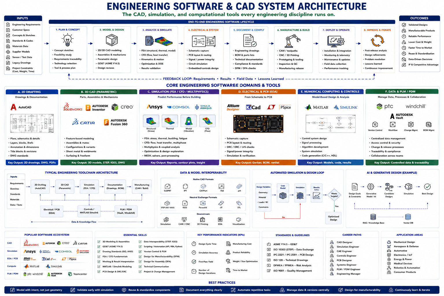
Hover, tap, or focus any component on the drawing (or a circuit below it) for details. Click to pin; move away or click again to clear.
Component Reference
Every component in the diagram above, grouped by section, with its role and the relevant standard.
Inputs
Engineering Requirements
The functional, performance, and regulatory requirements a design must satisfy. Requirements are the first input to the lifecycle and are traced through concept, design, and validation so nothing gets built that was not actually asked for.
Customer Specs
Customer-facing specifications — performance targets, form factor, price point, and preferences — that shape the concept before any CAD work starts.
Concepts & Sketches
Early hand sketches and rough concept ideation that precede formal CAD modeling — the raw creative input that Plan & Concept converts into a feasible direction.
Standards & Codes
Applicable industry standards and codes (ASME, ISO, IPC, and sector-specific regulations) that constrain geometry, tolerances, documentation, and process from day one.
📘 ASME Y14.5 · ISO 128Materials Data
Material property data — strength, stiffness, thermal, and cost — that feeds parametric CAD models and simulation setups so analysis reflects real material behavior.
Supplier Models
CAD models and catalog data supplied by vendors for off-the-shelf components (fasteners, motors, connectors) — imported via neutral formats so they drop into the assembly.
Sensor / Test Data
Measured data from prototypes, test rigs, or field sensors used to validate or correlate simulation results and feed the feedback loop back into design.
Legacy Drawings
Existing 2D drawings or 3D models from prior product generations that get reused, revised, or reverse-engineered rather than redrawn from scratch.
Project Constraints (Cost, Weight, Time)
The hard business constraints — target cost, weight budget, and schedule — that every downstream decision (tool choice, material, design iteration count) gets balanced against.
Outcomes
Validated Designs
Designs that have been confirmed against requirements through simulation and physical test before committing to manufacturing — the direct payoff of the Analyze & Simulate step.
Manufacturable Products
Products engineered with DFM/DFA discipline so they can actually be built at the intended volume and cost, not just modeled on screen.
Reliable Performance
Products that perform to specification in the field over their service life, the result of upstream FEA/CFD validation and DFMEA risk analysis.
Lower Cost & Weight
Cost and weight reduced through optimization loops and simulation-driven design exploration rather than over-engineered first-pass geometry.
Faster Time to Market
A shorter path from concept to shipped product, enabled by parametric CAD reuse, automated simulation loops, and streamlined PLM/PDM change processes.
Reuse & Standardization
Standardized parts, assemblies, and templates that get reused across projects, cutting redundant design work and easing supply-chain consolidation.
Data-Driven Decisions
Design and business decisions grounded in simulation results, KPI tracking, and PLM traceability rather than intuition alone.
IP & Competitive Advantage
Controlled, versioned design data and documented engineering know-how that becomes protectable intellectual property and a durable competitive edge.
Engineering Software Lifecycle
1. Plan & Concept
Concept sketches, feasibility study, requirements traceability, technology selection, and tool & process planning — the step that turns raw requirements into a chosen direction and toolchain before CAD work begins.
2. Model & Design
2D/3D CAD modeling, assemblies & mechanisms, parametric design, GD&T (ASME Y14.5), and design reviews — the core modeling step spanning both 2D drafting and 3D parametric CAD domains.
📘 ASME Y14.53. Analyze & Simulate
FEA (structural, thermal, modal), CFD (flow, heat transfer), kinematics & motion, optimization & DOE, and results validation — predicting real-world performance before a single part is cut.
4. Electrical & System
Schematic capture, PCB layout & routing, signal/power integrity, circuit simulation, and embedded/controls design — the electrical and systems-engineering thread running parallel to mechanical design.
5. Document & Comply
Engineering drawings, BOM & parts lists, technical documentation, compliance & standards, and DFM/DFA checks — converting a validated design into the record of truth manufacturing and quality will build from.
6. Manufacture & Build
CAM/toolpaths, CNC/3D printing, prototyping & tooling, inspection & QC, and manufacturing release — turning documented designs into physical parts.
7. Deploy & Operate
Installation & integration, monitoring & telemetry, maintenance & updates, field data collection, and performance tracking — the in-service life of the product feeding real-world data back upstream.
8. Improve & Iterate
Post-release analysis, design refinements, problem resolution, lessons learned, and continuous improvement — closing the loop so field experience drives the next design cycle.
Feedback Loop
The dashed feedback loop threading the whole lifecycle: requirements refinements, simulation results, field data, and lessons learned all flow back to Plan & Concept so the next iteration starts smarter than the last.
2D Drafting
2D Drafting — AutoCAD
AutoCAD is the industry-standard 2D drafting platform for plans, schematics, and construction/manufacturing details — layers, blocks, xrefs, annotation, and title blocks built around the DWG format.
2D Drafting — Drawing Sample
A representative 2D drawing sheet — plan/schematic view with layered geometry, dimensioning, and a title block — the deliverable format 2D drafting exists to produce.
2D Drafting — Capabilities & Key Output
Core 2D drafting capabilities: plans/schematics/details, layers/blocks/xrefs, annotation & dimensions, title blocks & revisions, and DWG standards. Key output: 2D drawings, DWG files, and PDFs for fabrication and permitting.
3D CAD (Parametric)
3D CAD — SolidWorks / Inventor / Creo
SolidWorks, Autodesk Inventor, and PTC Creo are leading parametric 3D CAD platforms for feature-based part and assembly modeling with full history-based editing.
3D CAD — CATIA / Fusion 360
Dassault Systèmes CATIA (large-assembly aerospace/automotive-grade CAD) and Autodesk Fusion 360 (cloud-native, integrated CAD/CAM/simulation) round out the major parametric CAD platforms.
3D CAD — Capabilities & Key Output
Core 3D CAD capabilities: feature-based modeling, assemblies & mates, configurations & variants, sheet metal & weldments, and surfacing & freeform geometry. Key output: 3D models plus STEP, IGES, and DWG exchange files.
Simulation (FEA/CFD/Multiphysics)
Simulation — Ansys / COMSOL / Simulia Abaqus
Ansys, COMSOL Multiphysics, and Dassault Simulia Abaqus are the leading FEA/CFD/multiphysics simulation suites, used to predict structural, thermal, and flow performance before a physical prototype exists.
Simulation — Structural / Thermal / Modal / CFD Results
The four common simulation result types shown as contour plots: structural (stress), thermal, modal (vibration), and CFD (flow) — each visualizing a different physics domain over the same geometry.
Simulation — Capabilities & Key Output
Core simulation capabilities: FEA for stress/thermal/buckling/fatigue, CFD for flow/heat transfer/multiphase, multiphysics & coupled analysis, optimization & design exploration, and meshing/solvers/post-processing. Key output: reports, contour plots, and engineering insight.
Electrical & PCB (EDA)
Electrical & PCB — Altium / KiCad / PSpice
Altium Designer, the open-source KiCad, and PSpice cover the electronic design automation stack from schematic capture through PCB layout and circuit simulation.
Electrical & PCB — PCB Board Photo
A populated printed circuit board — the physical output of the EDA workflow, with routed copper traces and mounted components matching the schematic and layout files.
Electrical & PCB — Capabilities & Key Output
Core EDA capabilities: schematic capture, PCB layout & routing, DRC/ERC/LVS checks, signal/power integrity, and simulation & verification. Key output: Gerber files, BOM, and netlist ready for fabrication.
📘 IPC-2221 / IPC-2581Numerical Computing & Controls
Numerical Computing — MATLAB / Simulink
MATLAB and Simulink are the standard platform for numerical computing, algorithm development, and model-based design of control systems and dynamic behavior.
Numerical Computing — Control System Diagram
A Simulink-style block diagram representing a closed-loop control system — the model-based design artifact that gets simulated, tuned, and then auto-generated into deployable code.
Numerical Computing — Capabilities & Key Output
Core capabilities: control system design, signal processing, algorithm development, system simulation, and code generation (C/C++, HDL). Key output: models, generated code, and simulation results.
Data & PLM/PDM
Data & PLM/PDM — ptc Windchill
PTC Windchill is a leading PLM platform for managing engineering data, change processes, and cross-team collaboration across the product lifecycle.
Data & PLM/PDM — Autodesk Vault
Autodesk Vault is a product data management (PDM) tool that version-controls CAD files, manages check-in/check-out, and links design data to downstream processes.
Data & PLM/PDM — Version Control / Workflow / Change Mgmt / BOM Mgmt
The four core PDM/PLM functions: version control (file history & revisions), workflow (approval routing), change management (ECO/ECR processes), and BOM management (structured parts lists tied to revisions).
Data & PLM/PDM — Capabilities & Key Output
Core capabilities: centralized data management, access control & security, change & release processes, traceability & compliance, and collaboration across teams. Key output: controlled data and full traceability from concept to as-built.
Typical Engineering Toolchain Architecture
Toolchain — Inputs
The inputs feeding a typical toolchain: requirements, sketches, standards, materials data, and test/data files — the same categories detailed in the Inputs panel, shown here as they enter the tool pipeline.
Toolchain — 2D Drafting (AutoCAD)
The 2D drafting stage (AutoCAD) is typically the first tool stage for schematics and layout drawings before or alongside 3D modeling.
Toolchain — 3D CAD (Parametric)
The parametric 3D CAD stage builds the geometric model that simulation, documentation, and manufacturing all consume downstream.
Toolchain — Simulation (FEA/CFD)
The simulation stage validates the 3D CAD model against structural, thermal, and flow requirements before it is documented and released.
Toolchain — Documentation (Drawings, BOM)
The documentation stage generates drawings and the bill of materials from the validated 3D model — the formal record used for manufacturing and compliance.
Toolchain — Manufacturing (CAM / Build)
The manufacturing stage converts documentation into CAM toolpaths and build instructions for CNC, 3D printing, or assembly.
Toolchain — Electrical / PCB (EDA)
The electrical/PCB (EDA) tool track branches beneath 2D drafting and 3D CAD, feeding schematic and PCB layout data back into the documentation and manufacturing stages.
Toolchain — Controls / MATLAB Simulink
The controls tool track (MATLAB/Simulink) branches beneath simulation, handling model-based control-system design that feeds back into the CAE/simulation workflow.
Toolchain — PLM / PDM (Vault, Windchill)
The PLM/PDM tool track (Vault, Windchill) branches beneath documentation and manufacturing, versioning and controlling the data that flows through the whole toolchain.
Toolchain — Data & Knowledge Flow
The bidirectional data & knowledge flow spanning the entire toolchain — geometry, results, and revisions move forward and backward across every stage rather than in one direction only.
Data & Model Interoperability
Native CAD Format — SLDPRT (SolidWorks)
SLDPRT is SolidWorks’ native part-file format, carrying full parametric feature history — editable only in SolidWorks or via translators.
Native CAD Format — IPT (Inventor)
IPT is Autodesk Inventor’s native part-file format, preserving parametric features and design history specific to the Inventor modeling kernel.
Native CAD Format — CATPart (CATIA)
CATPart is CATIA’s native part-file format, used across aerospace and automotive OEM supply chains built on Dassault’s CAD ecosystem.
Native CAD Format — .f3d (Fusion 360)
.f3d is Autodesk Fusion 360’s native cloud-based model format, storing full timeline history in Autodesk’s cloud data service.
Native CAD Format — .prt (Creo)
.prt is PTC Creo’s native part-file format, carrying Creo’s parametric feature tree and constraint history.
Neutral Exchange Format — STEP (ISO 10303)
STEP (ISO 10303) is the universal neutral CAD exchange format, preserving solid geometry (and increasingly PMI/GD&T) across virtually any CAD platform.
📘 ISO 10303Neutral Exchange Format — IGES
IGES is an older neutral exchange format, still used for surface and wireframe geometry exchange where STEP support is unavailable.
Neutral Exchange Format — Parasolid
Parasolid is the solid-modeling kernel format shared by several major CAD systems (SolidWorks, NX, Solid Edge), enabling higher-fidelity exchange than STEP in kernel-compatible tools.
Neutral Exchange Format — JT
JT is a lightweight, ISO-standardized format used heavily in automotive/aerospace for large-assembly visualization, review, and PLM data exchange.
Neutral Exchange Format — STL
STL represents geometry as a triangulated surface mesh — the standard input format for 3D printing and many rapid-prototyping workflows.
Downstream — Simulation
Neutral-format geometry gets imported into FEA/CFD simulation tools for meshing and analysis, often requiring simplified or cleaned-up STEP data.
Downstream — CAM / CNC
CAM software consumes STEP or Parasolid geometry to generate CNC toolpaths for machining.
Downstream — 3D Printing
Additive manufacturing (3D printing) slicers consume STL (or increasingly 3MF) mesh geometry to build layer-by-layer toolpaths.
Downstream — EDA
Mechanical enclosure geometry is exchanged with EDA/PCB tools (via STEP or IDF) so board outlines and component keep-outs match the physical housing.
Downstream — Visualization
Lightweight formats (JT, glTF, or STL) feed visualization, marketing renders, and large-assembly review tools without needing full parametric CAD data.
Automated Simulation & Design Loop
Design Variables
The parameters that define a design instance — geometry, material, loads/boundary conditions, and constraints — the inputs an automated optimization loop varies on each pass.
CAD Model
The parametric CAD model rebuilt automatically from the current set of design variables — the geometric instance that gets handed to simulation each loop iteration.
Simulation
An automated FEA/CFD simulation run against the current CAD instance, producing the performance data used to judge whether this design iteration is good enough.
Results
The KPI results extracted from the simulation run — stress, deflection, flow, or whatever metric the design is being optimized against.
Meets Targets? (Decision)
The decision gate comparing simulation results against target KPIs. A "No" loops the design variables back for another automated pass; a "Yes" releases the design as optimized.
Optimized Design
The design instance that passed the target check — the automated loop’s final output, ready to move into documentation and manufacturing.
AI & Generative Design
Design Goals & Constraints
The design goals and constraints (load cases, material, manufacturing method, weight/cost targets) that seed a generative-design run, analogous to design variables in the classic optimization loop but framed as objectives for an AI model.
Generative Model / AI
A generative-design or topology-optimization AI model that proposes candidate geometries from the stated goals and constraints, often informed by a retrieval layer over prior designs.
Candidate Designs
The set of candidate geometries produced by the generative model — multiple design options that trade off mass, stiffness, and manufacturability differently.
Simulation (AI Loop)
Each candidate design is run through simulation to validate structural, thermal, or flow performance before a best design is selected — the same simulation engines used elsewhere in the lifecycle.
Best Design
The candidate design selected as the best fit against goals and simulation results — the generative-design workflow’s equivalent of the classic loop’s "Optimized Design."
RAG / Knowledge Base
A retrieval-augmented-generation knowledge base of past designs, standards, and lessons learned that grounds the generative model’s proposals in real engineering precedent rather than pure generation.
Vector DB
A vector database storing embeddings of prior designs and documents, powering the similarity search that the RAG/Knowledge Base layer performs for the generative model.
Popular Software Ecosystem
CAD — SolidWorks
SolidWorks — one of the most widely taught and deployed parametric mechanical CAD platforms across industry.
CAD — Autodesk Inventor
Autodesk Inventor — Autodesk’s parametric mechanical CAD platform, tightly integrated with the Autodesk product data ecosystem including Vault.
CAD — Creo
PTC Creo — a long-established parametric CAD platform with strength in large-assembly and sheet-metal design.
CAD — CATIA
Dassault Systèmes CATIA — the dominant CAD platform in aerospace and automotive OEM design chains.
Simulation — Ansys
Ansys — a comprehensive multiphysics simulation suite covering structural, thermal, fluid, and electromagnetic analysis.
Simulation — Simulia Abaqus
Dassault Simulia Abaqus — a powerful nonlinear FEA solver widely used for advanced structural and materials analysis.
Simulation — COMSOL
COMSOL Multiphysics — a platform built specifically around coupling multiple physics domains in a single simulation.
Simulation — SolidWorks Simulation
SolidWorks Simulation — the FEA add-in embedded directly in SolidWorks CAD, lowering the barrier for design-integrated analysis.
EDA/PCB — Altium Designer
Altium Designer — a professional-grade PCB design suite covering schematic capture, layout, and manufacturing output.
EDA/PCB — KiCad
KiCad — a free, open-source PCB design tool that has become production-grade enough for professional and hobbyist use alike.
EDA/PCB — PSpice
PSpice — a SPICE-based analog and mixed-signal circuit simulator used to verify circuit behavior before layout.
Compute — MATLAB
MATLAB — the standard numerical computing environment for algorithm development, data analysis, and engineering scripting.
Compute — Simulink
Simulink — MATLAB’s block-diagram environment for model-based design and simulation of dynamic and control systems.
PLM/PDM — ptc Windchill
PTC Windchill — an enterprise PLM platform for managing product data, change processes, and lifecycle collaboration.
PLM/PDM — Autodesk Vault
Autodesk Vault — a product data management tool tightly integrated with Autodesk Inventor and the wider Autodesk CAD ecosystem.
PLM/PDM — Teamcenter
Siemens Teamcenter — an enterprise PLM platform used widely in large manufacturers for end-to-end product lifecycle management.
Skills & KPIs
Essential Skills — Modeling, Standards & Simulation
Core hands-on skills: 3D modeling & assemblies, GD&T (ASME Y14.5), drawing standards (ISO, ANSI), FEA/CFD fundamentals, meshing & result interpretation, MATLAB/Simulink modeling, and PCB design & DRC/ERC.
📘 ASME Y14.5Essential Skills — Interop, Scripting & Process
Process and cross-cutting skills: data interoperability (STEP, IGES), scripting/automation (API, VBA, Python), version control & PLM, design for manufacturability (DFM), design for assembly (DFA), technical communication, and project & change management.
KPI — Design Cycle Time
Design Cycle Time measures how long it takes to move from concept through a released design — a primary indicator of process efficiency.
KPI — Simulation Accuracy
Simulation Accuracy measures how closely FEA/CFD predictions correlate with physical test results, validating whether the simulation setup is trustworthy.
KPI — First-Pass Yield
First-Pass Yield tracks the percentage of designs or builds that meet requirements without requiring rework — a proxy for upstream design quality.
KPI — Number of Design Iterations
Number of Design Iterations counts how many design-analyze-revise loops were needed to reach an acceptable design — fewer iterations generally means a more mature process.
KPI — Manufacturing Cost
Manufacturing Cost tracks the per-unit cost to produce a design, balancing material, process, and labor against the target set in the constraints input.
KPI — Product Reliability
Product Reliability measures failure rate or mean time between failures in the field, the ultimate test of whether upstream validation worked.
KPI — Weight / Size Optimization
Weight/Size Optimization tracks how much mass or envelope was removed through optimization loops and generative design relative to a baseline.
KPI — Time to Market
Time to Market measures the total duration from initial concept to product launch — the business-level KPI that design cycle time and first-pass yield feed into.
Standards & Guidelines
ASME Y14.5 — GD&T
ASME Y14.5 defines Geometric Dimensioning and Tolerancing (GD&T) — the standard symbology for specifying allowable geometric variation on engineering drawings.
📘 ASME Y14.5ISO 10303 (STEP) — Data Exchange
ISO 10303, commonly known as STEP, is the international standard for exchanging 3D CAD geometry (and increasingly PMI) between different CAD systems.
📘 ISO 10303IPC-2221 / IPC-2581 — PCB Design
IPC-2221 sets generic PCB design and construction requirements, while IPC-2581 standardizes the digital data exchange format between PCB design and fabrication.
📘 IPC-2221 / IPC-2581ISO 128 — Technical Drawings
ISO 128 defines the general principles of presentation for technical drawings — line types, views, and conventions used across 2D drafting.
📘 ISO 128DFMEA / PFMEA — Risk Analysis
Design and Process Failure Mode and Effects Analysis (DFMEA/PFMEA) are structured risk-analysis methods for identifying and mitigating potential failure modes before they reach production.
ISO 9001 — Quality Management
ISO 9001 is the international standard for quality management systems, underpinning the documented processes and traceability that engineering software workflows must support.
Career Paths & Application Areas
Career Path — CAD Designer
CAD Designer — builds and maintains 2D drawings and 3D parametric models, the entry point into most engineering software career paths.
Career Path — Simulation Engineer
Simulation Engineer — runs and interprets FEA/CFD analyses to validate designs against structural, thermal, and flow requirements.
Career Path — CAE Engineer
CAE Engineer — applies computer-aided engineering tools broadly across simulation, optimization, and multiphysics analysis, often spanning multiple domains.
Career Path — Controls Engineer
Controls Engineer — designs and simulates control systems using MATLAB/Simulink and related model-based design tools.
Career Path — PCB Designer
PCB Designer — creates schematics and PCB layouts using EDA tools, translating circuit design into a manufacturable board.
Career Path — Systems Engineer
Systems Engineer — integrates mechanical, electrical, and software subsystems, managing requirements traceability across the whole product.
Career Path — PLM/PDM Engineer
PLM/PDM Engineer — administers the product data management system, governing version control, workflows, and change processes.
Career Path — Engineering Manager
Engineering Manager — leads engineering teams and owns the process, tooling, and KPI decisions across the software lifecycle.
Application Area — Mechanical Design
Mechanical Design — general product and machine design, the broadest application area for CAD, simulation, and PLM tools.
Application Area — Aerospace & Defense
Aerospace & Defense — high-reliability design work leaning heavily on CATIA-class CAD, rigorous FEA validation, and strict PLM traceability.
Application Area — Automotive
Automotive — vehicle and component design at high volume, driving heavy investment in simulation, DFM, and PLM change control.
Application Area — Electronics / IoT
Electronics/IoT — PCB and embedded product design combining EDA tools with mechanical enclosure CAD.
Application Area — Energy & Power
Energy & Power — equipment and infrastructure design for power generation and distribution, leaning on simulation for thermal and structural performance.
Application Area — Medical Devices
Medical Devices — highly regulated product design requiring rigorous documentation, DFMEA, and traceability through PLM.
Application Area — Robotics & Automation
Robotics & Automation — mechatronic system design spanning mechanical CAD, controls (MATLAB/Simulink), and embedded electronics.
Application Area — Consumer Products
Consumer Products — high-volume product design where cost, manufacturability, and time to market dominate tool and process decisions.
Best Practices
Best Practice — Model with Intent, Not Just Geometry
Model with intent, not just geometry: build parametric features and constraints that capture design logic, not just the final shape, so models stay editable as requirements change.
Best Practice — Validate Early with Simulation
Validate early with simulation: run FEA/CFD checks against a design as soon as geometry is stable, rather than waiting for a physical prototype to find problems.
Best Practice — Reuse & Standardize Components
Reuse & standardize components: maintain a library of proven parts and templates so new designs build on validated work instead of starting from zero.
Best Practice — Document Everything Clearly
Document everything clearly: keep drawings, BOMs, and technical documentation unambiguous so manufacturing and quality never have to guess intent.
Best Practice — Automate Repetitive Tasks
Automate repetitive tasks: use scripting and APIs (VBA, Python) to automate repetitive modeling, drawing, and data-entry work that eats engineering time.
Best Practice — Manage Data & Versions Centrally
Manage data & versions centrally: route all engineering data through PLM/PDM so there is a single, traceable source of truth instead of scattered local files.
Best Practice — Design for Manufacturability
Design for manufacturability: check tolerances, draft angles, and process capability against the intended manufacturing method throughout design, not after release.
Best Practice — Continuously Learn & Iterate
Continuously learn & iterate: feed field data and lessons learned back into the process and tooling so each design cycle starts from a stronger baseline.
Connections & Flows
The signal and data flows that tie the diagram together — each shown as a colored line in the legend above.
Feedback Loop
The lifecycle-wide feedback loop carrying requirements refinements, simulation results, field data, and lessons learned back to Plan & Concept — the mechanism that makes the 8-step lifecycle a loop rather than a one-way pipeline.
Data & Knowledge Flow
The bidirectional data & knowledge flow spanning the Typical Engineering Toolchain Architecture — geometry, results, and revisions move forward and backward across 2D drafting, 3D CAD, simulation, documentation, and manufacturing rather than in a single direction.
Automated Design-Loop Iteration
The "No" path in the Automated Simulation & Design Loop, sending design variables back for another automated pass when simulation results do not meet targets.