Robotics & Automation Engineering System Architecture
The full 8-step end-to-end robotics & automation lifecycle (concept & feasibility, system design, engineering & simulation, component selection, integration & build, testing & commissioning, deploy & operate, and optimize & improve), the six core disciplines that make up the practice (robot types & kinematics, ROS/ROS2 software stack, machine vision & perception, cobots & safety, controllers & automation, and prototyping & embedded), a typical automated cell architecture, a robot software stack example, and an AI/RAG integration example showing how robots, controllers, vision, and data connect in production. Hover, tap, or focus any component for its description and standard reference.
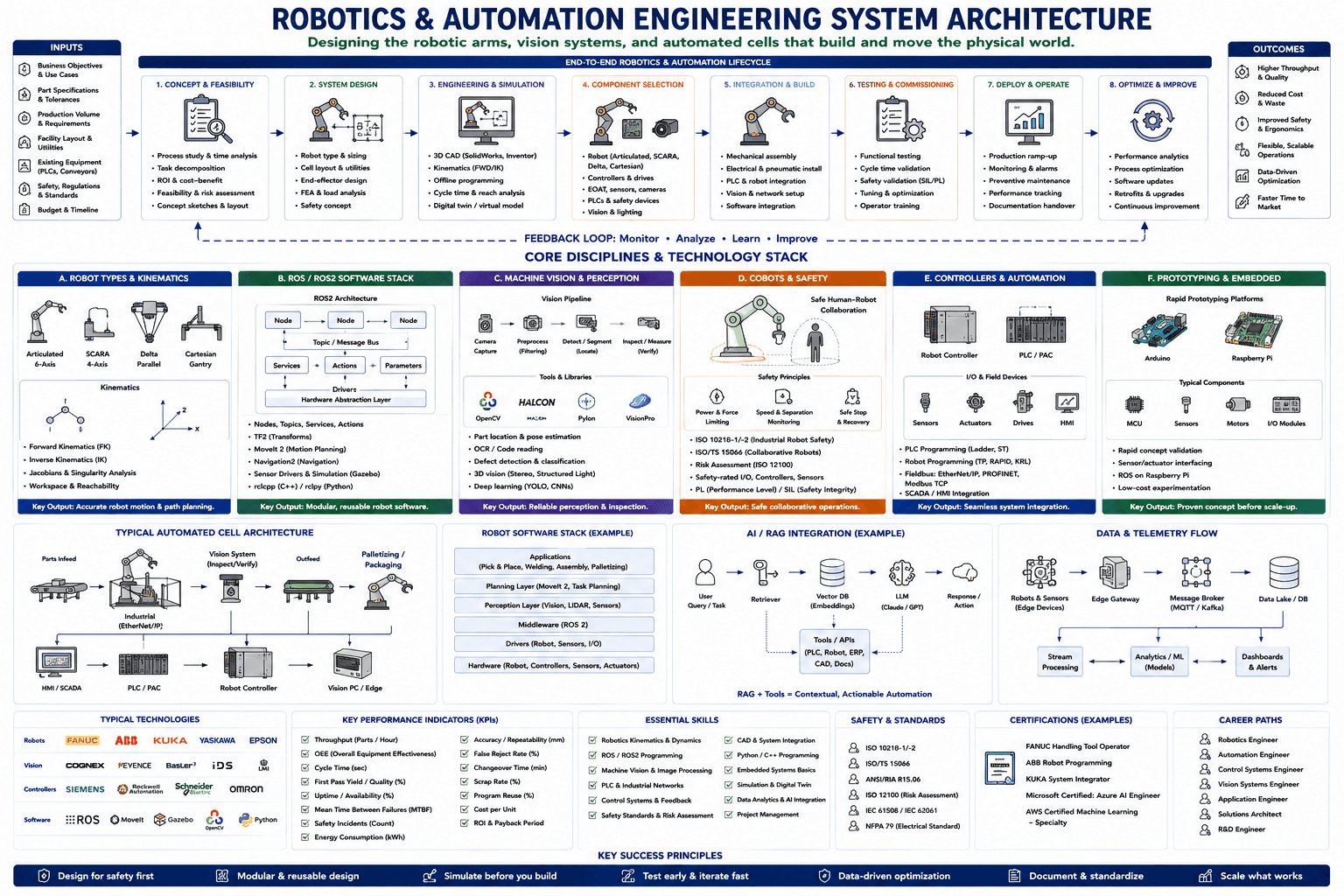
Hover, tap, or focus any component on the drawing (or a circuit below it) for details. Click to pin; move away or click again to clear.
Component Reference
Every component in the diagram above, grouped by section, with its role and the relevant standard.
Inputs
Business Objectives & Use Cases
The business case and target use cases driving the project — the starting input every downstream decision, from robot selection to ROI review, is judged against.
Part Specifications & Tolerances
The geometry, material, weight, and dimensional tolerances of the parts the cell must handle — sets the accuracy and repeatability bar for robot and end-of-arm-tooling selection.
Production Volume & Requirements
The required parts-per-hour, batch sizes, and takt time — drives whether a single robot cell or a multi-cell line is justified, and shapes the cycle-time budget for step 3 (Engineering & Simulation).
Facility Layout & Utilities
Available floor space, ceiling height, power, compressed air, and network drops — a hard physical constraint on cell layout and reach requirements during system design.
Existing Equipment (PLCs, Conveyors)
Legacy PLCs, conveyors, and machinery the new automation must interface with — rarely does a cell get built into a truly empty line, so integration constraints shape controller and fieldbus choices.
Safety, Regulations & Standards
The safety codes and regulatory standards (ISO 10218, ISO/TS 15066, ANSI/RIA R15.06) the finished cell must comply with — a first-class design input, not an afterthought.
Budget & Timeline
The capital budget and project timeline every design decision must fit inside — the practical ceiling that turns an ideal cell design into a shippable one.
Outcomes
Higher Throughput & Quality
Faster cycle times and more consistent part quality than manual production — the core deliverable every stage of the lifecycle, from component selection to testing, exists to protect.
Reduced Cost & Waste
Lower labor and rework cost plus reduced scrap from consistent, repeatable robot motion — the financial return that justifies the automation investment.
Improved Safety & Ergonomics
Removing workers from hazardous, repetitive, or ergonomically harmful tasks — the direct payoff of the Cobots & Safety discipline and the risk-assessment work done up front.
Flexible, Scalable Operations
A cell architecture that can be reprogrammed for new parts or scaled with additional stations rather than rebuilt — the payoff of modular design and reusable robot software.
Data-Driven Optimization
Live production and telemetry data feeding continuous process improvement — the direct output of the Data & Telemetry Flow pipeline further down the diagram.
Faster Time to Market
Shorter time from concept to production ramp-up, enabled by digital twins, offline programming, and simulation that de-risk the build before it touches the shop floor.
Robotics & Automation Lifecycle
1. Concept & Feasibility
Studies the current process and time analysis, decomposes the task, assesses ROI and cost-benefit, evaluates feasibility and risk, and sketches an initial concept and layout — the step that decides whether the project is worth pursuing before any engineering begins.
2. System Design
Selects the robot type and sizing, plans cell layout and utilities, designs the end-effector concept, runs FEA and load analysis, and defines the safety concept — the blueprint every later engineering stage builds against.
3. Engineering & Simulation
Builds 3D CAD models (SolidWorks, Inventor), works out forward/inverse kinematics, offline-programs robot paths, analyzes cycle time and reach, and builds a digital twin or virtual model to validate the design before hardware is ordered.
4. Component Selection
Selects the robot architecture (Articulated, SCARA, Delta, Cartesian), controllers and drives, end-of-arm tooling, sensors and cameras, PLCs and safety devices, and vision and lighting hardware.
5. Integration & Build
Performs mechanical assembly, electrical and pneumatic installation, PLC and robot integration, vision and network setup, and software integration — turning selected components into a working cell.
6. Testing & Commissioning
Runs functional testing, validates cycle time, performs safety validation against SIL/PL targets, tunes and optimizes the cell, and trains operators before handing the line to production.
📘 IEC 61508 / IEC 62061 (SIL)7. Deploy & Operate
Ramps production up to full rate, monitors and alarms the running cell, executes preventive maintenance, tracks performance, and hands over documentation to the operating team.
8. Optimize & Improve
Analyzes performance data, optimizes the process, pushes software updates, retrofits and upgrades hardware, and drives continuous improvement — feeding straight back into step 1 via the feedback loop below.
Feedback Loop: Monitor · Analyze · Learn · Improve
The dashed feedback loop that carries monitoring signal, analysis, and lessons learned from step 8 back to step 1 — the mechanism that makes the robotics and automation lifecycle a genuine loop rather than a one-way pipeline.
Robot Types & Kinematics
A. Robot Types & Kinematics — Architectures & Kinematics
The four dominant robot architectures — Articulated (6-axis), SCARA (4-axis), Delta (parallel), and Cartesian (gantry) — alongside the kinematics diagrams (a 2-link planar arm and an XYZ frame) used to derive forward and inverse kinematics for each.
A. Robot Types & Kinematics — Key Output
Forward kinematics (FK), inverse kinematics (IK), Jacobians and singularity analysis, and workspace & reachability analysis. Key output: accurate robot motion & path planning.
ROS/ROS2 Software Stack
B. ROS/ROS2 Software Stack — Architecture
The ROS2 architecture: nodes communicating over a topic/message bus, exposing services, actions, and parameters, talking down through drivers to a hardware abstraction layer — the standard middleware pattern for robot software.
B. ROS/ROS2 Software Stack — Key Output
Nodes/topics/services/actions, TF2 transforms, MoveIt 2 for motion planning, Navigation2 for mobile navigation, sensor drivers and simulation via Gazebo, and the rclcpp (C++) / rclpy (Python) client libraries. Key output: modular, reusable robot software.
Machine Vision & Perception
C. Machine Vision & Perception — Vision Pipeline
The vision pipeline — camera capture, preprocessing/filtering, detect/segment (locate), and inspect/measure (verify) — plus the tool libraries used to build it: OpenCV, HALCON, Pylon, and VisionPro.
C. Machine Vision & Perception — Key Output
Part location & pose estimation, OCR/code reading, defect detection & classification, 3D vision (stereo, structured light), and deep learning (YOLO, CNNs). Key output: reliable perception & inspection.
Cobots & Safety
D. Cobots & Safety — Safe Human-Robot Collaboration
The safe human-robot collaboration model and its three safety principles: power & force limiting, speed & separation monitoring, and safe stop & recovery — the foundation of collaborative robot (cobot) deployment.
📘 ISO/TS 15066 (Collaborative Robots)D. Cobots & Safety — Standards & Key Output
ISO 10218-1/-2 (industrial robot safety), ISO/TS 15066 (collaborative robots), risk assessment per ISO 12100, safety-rated I/O, controllers and sensors, and Performance Level (PL) / Safety Integrity Level (SIL) ratings. Key output: safe collaborative operations.
📘 ISO 10218-1/-2Controllers & Automation
E. Controllers & Automation — Robot Controller & PLC/PAC
The robot controller and PLC/PAC that run the cell, plus the I/O & field devices row — sensors, actuators, drives, and HMI — that the controllers read and command.
E. Controllers & Automation — Key Output
PLC programming (Ladder, Structured Text), robot programming (TP, RAPID, KRL), fieldbus networks (EtherNet/IP, PROFINET, Modbus TCP), and SCADA/HMI integration. Key output: seamless system integration.
Prototyping & Embedded
F. Prototyping & Embedded — Rapid Prototyping Platforms
Rapid prototyping platforms — Arduino and Raspberry Pi — and the typical components built around them: MCUs, sensors, motors, and I/O modules, used to validate concepts before committing to industrial-grade hardware.
F. Prototyping & Embedded — Key Output
Rapid concept validation, sensor/actuator interfacing, running ROS on a Raspberry Pi, and low-cost experimentation. Key output: a proven concept before scale-up.
Typical Automated Cell Architecture
Parts Infeed
The infeed conveyor that stages incoming parts for the cell — the entry point of the automated cell, upstream of the robot.
Industrial Robot (EtherNet/IP)
The industrial robot arm inside its safety cage, networked over EtherNet/IP — the core actuator of the cell, picking parts from infeed and presenting them to the vision system.
Vision System (Inspect/Verify)
The machine-vision station that inspects and verifies each part in-line — the quality gate between the robot handling the part and it moving downstream to outfeed.
Outfeed
The outfeed conveyor carrying verified parts out of the cell toward palletizing or the next process step.
Palletizing / Packaging
A second robot arm performing palletizing or packaging — the final handling step before the finished load leaves the cell.
HMI / SCADA
The human-machine interface and SCADA screen giving operators visibility into and manual control over the cell — the top of the control stack.
PLC / PAC
The programmable logic/automation controller running the cell's discrete control logic — sequencing conveyors, interlocks, and safety circuits.
Robot Controller
The dedicated robot controller executing the taught or programmed motion path, coordinated with the PLC over the cell network.
Vision PC / Edge
The vision PC or edge compute unit running the inspection algorithms and returning pass/fail and pose data to the robot and PLC.
Robot Software Stack
Applications (Pick & Place, Welding, Assembly, Palletizing)
The application layer — pick & place, welding, assembly, and palletizing — the task-specific logic built on top of everything below it in the stack.
Planning Layer (MoveIt 2, Task Planning)
The planning layer, typically MoveIt 2, that turns a task goal into a collision-free motion plan and sequences task-level steps.
Perception Layer (Vision, LIDAR, Sensors)
The perception layer fusing vision, LIDAR, and other sensors into the state estimate the planning layer needs to plan around obstacles and locate parts.
Middleware (ROS 2)
ROS 2 as the middleware layer — the publish/subscribe messaging backbone that lets perception, planning, and drivers communicate without being tightly coupled.
Drivers (Robot, Sensors, I/O)
The driver layer translating ROS 2 commands into robot-specific, sensor-specific, and I/O-specific protocols — the boundary between software and hardware.
Hardware (Robot, Controllers, Sensors, Actuators)
The physical robot, controllers, sensors, and actuators the entire software stack ultimately exists to command.
AI/RAG Integration
User Query / Task
A natural-language query or task request from an engineer or operator — the trigger for the retrieval-augmented-generation pipeline that follows.
Retriever
The retrieval component that searches the vector database for passages most semantically relevant to the query — using embedding similarity rather than keyword matching.
Vector DB (Embeddings)
A vector database storing document embeddings — robot manuals, safety standards, maintenance logs — enabling fast approximate-nearest-neighbor search for the retriever.
LLM (Claude / GPT)
The large language model that generates the final response, grounded in both the user's query and the retrieved context — reducing hallucination versus an ungrounded model.
Response / Action
The generated response returned to the user, or, in an agentic flow, an action dispatched through the Tools/APIs layer — closing the loop from query to outcome.
Tools / APIs (PLC, Robot, ERP, CAD, Docs)
The external tools and APIs — PLC, robot, ERP, CAD, and documentation systems — that the retriever and LLM can call, turning RAG plus task context into contextual, actionable automation.
Data & Telemetry Flow
Robots & Sensors (Edge Devices)
The robots and sensors on the shop floor generating raw telemetry — position, force, cycle status, and process data — the origin point of the data pipeline.
Edge Gateway
The edge gateway that aggregates data from robots and sensors, does local pre-processing, and forwards it upstream to the message broker.
Message Broker (MQTT / Kafka)
A publish/subscribe message broker — MQTT or Kafka — decoupling data producers (edge gateways) from consumers (the data lake, stream processing, and analytics).
Data Lake / DB
The data lake or database persisting both raw and processed telemetry — the system of record analytics and ML models train and query against.
Stream Processing
Real-time stream processing that transforms and enriches telemetry as it arrives, feeding both analytics/ML and the stored data lake.
Analytics / ML (Models)
Analytics and ML models — predictive maintenance, anomaly detection, throughput forecasting — trained and served against the stream-processed and stored telemetry.
Dashboards & Alerts
Operator dashboards and alerting that surface analytics results and anomalies in real time — the point where the data pipeline reaches a human decision-maker.
Typical Technologies
FANUC
FANUC — one of the largest industrial robot manufacturers, widely used for material handling, welding, and assembly.
ABB
ABB — a major industrial robot and cobot manufacturer, known for its IRB line and RobotStudio offline programming software.
KUKA
KUKA — a leading German industrial robot manufacturer, known for the KR series and KRL programming language.
YASKAWA
Yaskawa Motoman — a major robot and servo/motion control manufacturer, widely used in welding and material handling.
EPSON
Epson — a leading manufacturer of SCARA robots, common in electronics assembly and precision pick-and-place.
Cognex
Cognex — a leading machine vision systems and barcode reading vendor for inspection and guidance applications.
Keyence
Keyence — a major vendor of vision sensors, laser measurement, and inspection systems.
Basler
Basler — a leading industrial camera manufacturer supplying imaging hardware for machine-vision pipelines.
IDS
IDS — an industrial camera manufacturer supplying USB and GigE vision cameras for automation.
LMI
LMI Technologies — a vendor of 3D laser scanning and profiling sensors used for inspection and guidance.
SIEMENS
Siemens — a major PLC and industrial automation vendor (SIMATIC line), widely used across discrete and process automation.
Rockwell Automation
Rockwell Automation — the vendor behind Allen-Bradley PLCs and the ControlLogix platform, dominant in North American manufacturing.
Schneider Electric
Schneider Electric — a major industrial automation and controller vendor (Modicon PLC line).
OMRON
Omron — a controller and sensor vendor widely used in machine automation and safety systems.
ROS
ROS/ROS2 — the dominant open-source robot software framework covering messaging, drivers, and tooling.
MoveIt
MoveIt — the standard ROS motion-planning framework for manipulator arms, handling kinematics, collision checking, and trajectory generation.
Gazebo
Gazebo — a physics-based robot simulator used to test ROS software and validate motion before deploying to real hardware.
OpenCV
OpenCV — the open-source computer vision library underlying most custom machine-vision pipelines.
Python
Python — the dominant scripting and rapid-prototyping language across robotics, vision, and data pipelines (rclpy, OpenCV, ML tooling).
Key Performance Indicators (KPIs)
Throughput (Parts / Hour)
The number of parts the cell produces per hour — the headline capacity metric tying directly back to the production-volume input.
OEE (Overall Equipment Effectiveness)
Overall Equipment Effectiveness — the composite of availability, performance, and quality that is the single most-used automation health metric.
Cycle Time (sec)
The time to complete one full cycle of the cell's operation — the number optimized during engineering & simulation and validated during commissioning.
First Pass Yield / Quality (%)
The percentage of parts that pass inspection on the first attempt without rework — a direct measure of process and vision-system quality.
Uptime / Availability (%)
The percentage of scheduled production time the cell is actually running — the availability term inside OEE.
Mean Time Between Failures (MTBF)
The average operating time between failures — a core reliability metric driving preventive-maintenance scheduling.
Safety Incidents (Count)
The count of recorded safety incidents in and around the cell — the metric every risk-assessment and cobot-safety decision ultimately exists to keep at zero.
Energy Consumption (kWh)
The energy the cell consumes per shift or per part — increasingly tracked alongside throughput as an operating-cost and sustainability metric.
Accuracy / Repeatability (mm)
Robot accuracy (how close to a commanded point it actually reaches) and repeatability (how consistently it returns to the same point) — the metric that sets the tolerance floor for part handling.
False Reject Rate (%)
The percentage of good parts incorrectly flagged as defective by the vision system — a false positive that wastes good product if not tuned out.
Changeover Time (min)
The time required to reconfigure the cell for a different part or product — a key driver of how flexible and scalable the operation really is.
Scrap Rate (%)
The percentage of parts scrapped as unusable — the direct cost signal of process or handling defects.
Program Reuse (%)
The percentage of robot program code and motion logic reused across products — a measure of how modular and reusable the robot software really is.
Cost per Unit
The fully loaded cost to produce one unit through the cell — the unit-economics figure that ties automation performance back to the business case.
ROI & Payback Period
Return on investment and the payback period for the automation capital outlay — the metric the original business-objectives input is ultimately judged against.
Essential Skills
Robotics Kinematics & Dynamics
Forward/inverse kinematics and rigid-body dynamics — the mathematical foundation for path planning, motion control, and robot selection.
ROS / ROS2 Programming
Practical fluency writing nodes, services, and actions on ROS/ROS2 — the default skill for modern robot software development.
Machine Vision & Image Processing
Building and tuning vision pipelines for inspection, guidance, and defect detection — the skill behind the Machine Vision & Perception discipline.
PLC & Industrial Networks
PLC programming and industrial network protocols (EtherNet/IP, PROFINET, Modbus) — the skill that ties the cell's controllers together.
Control Systems & Feedback
Feedback control theory applied to servo tuning, motion control, and process regulation across the cell.
Safety Standards & Risk Assessment
Applying ISO 12100 risk assessment and robot safety standards (ISO 10218, ISO/TS 15066) to real cell designs — a non-negotiable skill for anyone specifying a cell.
CAD & System Integration
CAD modeling of the robot, tooling, and layout, and the systems-integration skill to make selected components actually work together.
Python / C++ Programming
Programming fluency in Python and C++ — the two languages ROS, vision libraries, and most robot SDKs are built on.
Embedded Systems Basics
Working knowledge of microcontrollers, sensor interfacing, and firmware — the skill exercised directly in the Prototyping & Embedded discipline.
Simulation & Digital Twin
Building and using digital twins and simulators (Gazebo, offline programming tools) to validate a cell design before hardware is ordered.
Data Analytics & AI Integration
Applying analytics and AI/ML to cell telemetry — the skill behind the Data & Telemetry Flow and AI/RAG Integration panels.
Project Management
Running a robotics/automation project against the budget-and-timeline constraint set in the Inputs — scoping, scheduling, and vendor coordination.
Safety & Standards
ISO 10218-1/-2
ISO 10218-1/-2 — the core industrial robot safety standard, covering robot design (Part 1) and integration into a system (Part 2).
📘 ISO 10218-1/-2ISO/TS 15066
ISO/TS 15066 — the technical specification defining collaborative robot safety, including power/force limiting and speed & separation monitoring thresholds.
📘 ISO/TS 15066ANSI/RIA R15.06
ANSI/RIA R15.06 — the US national adoption of ISO 10218, the standard OSHA references for industrial robot safety compliance.
📘 ANSI/RIA R15.06ISO 12100 (Risk Assessment)
ISO 12100 — the general safety-of-machinery standard defining the risk-assessment and risk-reduction methodology that underlies robot-specific safety standards.
📘 ISO 12100IEC 61508 / IEC 62061
IEC 61508 (functional safety) and IEC 62061 (safety of machinery, electrical/electronic control systems) — the standards behind Safety Integrity Level (SIL) ratings used during testing & commissioning.
📘 IEC 61508 / IEC 62061NFPA 79 (Electrical Standard)
NFPA 79 — the US electrical standard for industrial machinery, governing the electrical design and installation of the cell's controllers and power distribution.
📘 NFPA 79Certifications (Examples)
FANUC Handling Tool Operator
A FANUC certification covering safe and effective operation of FANUC handling-tool robot systems.
ABB Robot Programming
An ABB certification covering RAPID programming and RobotStudio for ABB industrial robots.
KUKA System Integrator
A KUKA certification for engineers who design, program, and integrate KUKA robot cells.
Microsoft Certified: Azure AI Engineer
A Microsoft certification validating skills building and deploying AI solutions on Azure — relevant to the AI/RAG Integration and Data & Telemetry panels.
AWS Certified Machine Learning – Specialty
An AWS specialty certification validating the ability to design, build, and deploy machine learning solutions on AWS — relevant to the Analytics/ML stage of the data pipeline.
Career Paths
Robotics Engineer
Designs, builds, and programs robot systems end-to-end — the broadest role spanning kinematics, software, and integration.
Automation Engineer
Designs and commissions automated production cells — robots, PLCs, sensors, and the control logic tying them together.
Control Systems Engineer
Owns the feedback control loops, PLC/PAC logic, and controller tuning that keep the cell running to spec.
Vision Systems Engineer
Designs and tunes machine-vision pipelines for inspection, guidance, and quality — the role behind the Machine Vision & Perception discipline.
Application Engineer
Works with customers to adapt a vendor's standard robot cell or product to a specific application and production requirement.
Solutions Architect
Designs the end-to-end system architecture across mechanical, electrical, controls, and software — the role most exercised in step 2 (System Design) of the lifecycle.
R&D Engineer
Develops next-generation robot hardware, algorithms, or AI capabilities ahead of production deployment.
Key Success Principles
Design for safety first
Bake safety into the cell design from the first concept sketch — risk assessment and safety-rated hardware are design inputs, not a final review step.
Modular & reusable design
Design cells, fixtures, and robot programs to be modular and reusable across products — the difference between a one-off build and a scalable automation platform.
Simulate before you build
Validate reach, cycle time, and collision-free motion in a digital twin or simulator before committing to hardware — cheaper to fix in CAD than on the floor.
Test early & iterate fast
Start functional and safety testing as early as possible and iterate quickly — problems found during commissioning are far cheaper than problems found in production.
Data-driven optimization
Use the Data & Telemetry Flow pipeline's live metrics to drive continuous improvement decisions rather than guesswork.
Document & standardize
Document programs, wiring, and standard operating procedures so the cell can be maintained, changed over, and scaled by someone other than its original builder.
Scale what works
Once a cell design is proven in production, replicate it across lines and plants rather than redesigning from scratch each time.
Connections & Flows
The signal and data flows that tie the diagram together — each shown as a colored line in the legend above.
Feedback / Monitoring Loop
The dashed loop carrying monitoring signal, analysis, and lessons learned from step 8 (Optimize & Improve) back to step 1 (Concept & Feasibility) — the mechanism that makes the robotics and automation lifecycle a genuine loop rather than a one-way pipeline.
Process / Data Flow
The solid arrows tracing the primary path through each part of the diagram — the lifecycle stages, the automated cell architecture, the robot software stack, the AI/RAG pipeline, and the data & telemetry flow — showing the main direction motion, control, and data move.