Mechatronics Engineering System Architecture
The full 8-step end-to-end mechatronic design lifecycle (requirements & system definition, concept & system architecture, mechanical design, electrical & electronics design, sensor & signal integration, control & software development, system integration & testing, and deploy & operate & improve), the 6 core disciplines that meet in every mechatronic system — mechanical systems, actuators & power, electrical & electronics, sensors & measurement, control systems (PID), and embedded software — and the control-loop reference examples (a typical mechatronic architecture, the generic PID control loop, and a worked DC motor position-control example) that tie sensing, computation, and motion together. Hover, tap, or focus any component for its description and standard reference.
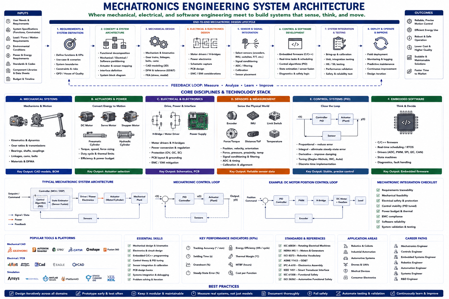
Hover, tap, or focus any component on the drawing (or a circuit below it) for details. Click to pin; move away or click again to clear.
Component Reference
Every component in the diagram above, grouped by section, with its role and the relevant standard.
Inputs
User Needs & Requirements
The starting point of the mechatronic design lifecycle — stakeholder needs, use cases, and the problem the system must solve. Everything downstream (specifications, architecture, and test criteria) traces back to these needs.
System Specifications (Functions, Constraints)
The translated, testable functions and constraints derived from user needs — performance targets, interfaces, and boundary conditions the design must satisfy. Feeds directly into Step 1 (Requirements & System Definition).
Load / Force / Motion Requirements
The forces, torques, speeds, and motion profiles the mechanism must deliver — the primary sizing input for actuators, gear trains, and structural members.
📘 ASME Y14.5 (GD&T)Environmental Conditions
The operating environment — temperature range, ingress protection, vibration, and duty cycle — that drives enclosure ratings, derating, and component selection across mechanical and electrical subsystems.
Power & Energy Requirements
Available supply voltage/current, battery capacity, or energy harvesting limits that bound actuator selection, drive electronics, and the overall power budget for the system.
Standards & Codes
The applicable standards — motor and electrical machine standards, safety and functional-safety codes, and industry-specific regulations — that constrain design choices and validation criteria from the outset.
📘 IEC 60034 / NEMA MG 1Component Libraries & Data Sheets
Vendor datasheets, CAD/electrical component libraries, and prior-design parts catalogs that speed selection and keep the design grounded in real, sourceable hardware.
Budget & Timeline
The cost target and development schedule that shape build-vs-buy decisions, prototyping strategy, and how many design-iteration cycles the project can afford.
Outcomes
Reliable, Precise Motion Control
The mechatronic system delivers accurate, repeatable motion — the direct payoff of well-tuned PID control, low-backlash mechanisms, and calibrated sensor feedback.
Efficient Energy Use
Actuator sizing, drive efficiency, and control-loop tuning that avoid over-provisioning translate directly into lower energy consumption per operating cycle — critical for battery-powered and duty-cycled systems.
Robust & Safe Operation
Electrical protection, control stability, and diagnostic/fault-handling logic that keep the system operating safely across its rated envelope and fail gracefully outside it.
📘 IEC 61508 (Functional Safety)Lower Cost & Higher Quality
Disciplined DFM/DFMA, tolerance stack-up analysis, and validated designs reduce bill-of-materials cost and manufacturing defects simultaneously rather than trading one for the other.
Scalable & Maintainable Solutions
Modular mechanical, electrical, and firmware architecture that supports product variants, field upgrades, and maintenance without a full redesign.
Faster Time to Market
Reused component libraries, early prototyping, and a disciplined 8-step lifecycle shorten the path from concept to field deployment.
Mechatronic Design Lifecycle
1. Requirements & System Definition
Define functions & KPIs, use-cases and scenarios, system boundaries, constraints & risks, and run QFD / House of Quality to translate stakeholder needs into engineering requirements. The foundation every later step is validated against.
2. Concept & System Architecture
Functional decomposition, mechanical/electrical/software partitioning, actuator & sensor mapping, interface definition, and a system block diagram — the architecture that every subsystem is designed against.
3. Mechanical Design
Mechanism & kinematics design, gear trains/linkages/belts/cams, 3D CAD modeling, DFM & tolerance stack-up (GD&T), and FEA (stress, modal) to validate the structure before it is built.
📘 ASME Y14.5 (GD&T)4. Electrical & Electronics Design
Motor drivers/H-bridges, power electronics, schematic capture, PCB design, and EMC/EMI considerations that turn the control concept into a buildable electrical system.
5. Sensor & Signal Integration
Select sensors (encoders, IMU, switches, force/torque, etc.), signal conditioning, ADC & filtering, calibration, and sensor placement — turning raw physical measurements into clean, usable data.
6. Control & Software Development
Embedded firmware (C/C++), real-time tasks & scheduling, control algorithms (PID), state estimation/sensor fusion, and diagnostics & safety logic — the "brain" that closes the loop between sensing and actuation.
7. System Integration & Testing
Bring-up & calibration, unit and integration testing, HIL/SIL (hardware/software-in-the-loop) testing, performance validation, and safety & reliability testing before the system leaves the lab.
📘 IEC 61508 (Functional Safety)8. Deploy & Operate & Improve
Field deployment, monitoring & logging, predictive maintenance, continuous improvement, and design iteration — the lifecycle closes the loop back into the feedback path below.
Feedback Loop: Measure · Analyze · Learn · Improve
Field data measured during deployment is analyzed and fed back into the next design iteration — the dashed loop that turns a one-shot design process into a continuously improving product.
Mechanical Systems
Mechanisms & Motion
Gearboxes, shaft couplings, and multi-link/robotic-arm mechanisms that transform and transmit motion — the physical skeleton that actuators drive and sensors measure.
📘 ASME Y14.5 (GD&T)Mechanical Systems — Design Considerations
Kinematics & dynamics, gear ratios & transmissions, bearings/shafts/couplings, linkages/cams/belts, and materials & DFMA — the checklist that governs every mechanical subsystem decision.
Key Output: CAD Models, BOM
The mechanical discipline hands off validated 3D CAD models and a bill of materials to electrical and control engineering — the physical envelope everything else is designed around.
Actuators & Power
Electric Motors (DC / Servo / Stepper)
DC motors (simple, continuous rotation), servo motors (closed-loop position/speed with high accuracy), and stepper motors (open-loop, discrete-step positioning) — the three most common electromechanical actuators in mechatronic design.
📘 NEMA MG 1 / IEC 60034 (Rotating Electrical Machines)Fluid Power Actuators (Pneumatic / Hydraulic)
Pneumatic cylinders (fast, compliant, air-driven) and hydraulic cylinders (very high force density, oil-driven) — linear actuators used where electric motors cannot economically deliver the required force or speed.
Actuators & Power — Sizing Considerations
Torque/speed/force sizing, duty cycle & thermal limits, and efficiency & power budget — the sizing checklist that determines whether an actuator survives continuous duty or is limited to intermittent use.
Key Output: Actuator Selection
A sized, sourced actuator (motor or cylinder) with a validated force/torque margin — the input the electrical/electronics discipline drives and the mechanical plant transmits to the load.
Electrical & Electronics
H-Bridge / Motor Driver
A four-switch H-bridge (or dedicated motor-driver IC) that switches current through a DC or stepper motor winding to control direction and, via PWM, speed/torque — the power-electronics core of Step 4.
📘 IPC-A-610 (Electronics Assembly)Power Supply
The regulated power-supply board that converts battery or mains input into the clean logic and motor-rail voltages the controller and drivers need — sized against the power budget set in Step 4.
Electrical & Electronics — Design Considerations
Motor drivers & H-bridges, power conversion & regulation, protection (over-voltage/over-current/short-circuit), PCB layout & grounding, and EMC/EMI mitigation — the checklist that keeps drive electronics reliable in the field.
Key Output: Schematics, PCB
A validated schematic and PCB layout — driver, power supply, and interface circuitry ready for fabrication and for the embedded software discipline to bring up.
Sensors & Measurement
Position & Motion Sensors (Encoder / IMU / Limit Switch)
Encoders (shaft position/velocity feedback), IMUs (orientation and acceleration), and limit switches (discrete end-of-travel detection) — the primary sensors that close position and motion control loops.
📘 IEEE 1451 (Smart Transducer Interface)Force, Distance & Temperature Sensors (Force/Torque / ToF / Temperature)
Force/torque sensors, time-of-flight distance sensors, and temperature sensors that measure the physical loads and environmental state a mechatronic system must respond to and protect itself from.
Sensors & Measurement — Design Considerations
Position/velocity/orientation, force/pressure/proximity/temperature, signal conditioning & filtering, ADC & timing, and calibration & alignment — the checklist that turns raw transducer output into trustworthy control-loop feedback.
📘 IEEE 1451 (Smart Transducer Interface)Key Output: Reliable Sensor Data
Calibrated, conditioned sensor data ready for the control-systems discipline to consume — the feedback signal every PID loop and state estimator depends on.
Control Systems (PID)
Control Loop: Controller (PID) → Actuator (Plant) → Sensor Feedback
The canonical feedback loop — a reference input r(t) drives a PID controller, whose output commands the actuator (plant) to produce output y(t), which a sensor measures and feeds back for the next correction.
📘 IEC 61508 (Functional Safety)Control Systems (PID) — Tuning Considerations
Proportional (reduce error), Integral (eliminate steady-state error), Derivative (improve damping), tuning methods (Ziegler–Nichols, IMC, Auto), and discrete-time implementation — the core of every closed-loop mechatronic controller.
Key Output: Stable, Precise Control
A tuned, stable control loop that tracks its setpoint with acceptable error, overshoot, and settling time — validated in Step 7 before the system is deployed.
Embedded Software
Microcontroller (Embedded Firmware)
The microcontroller that runs the mechatronic system’s firmware — reading sensors, executing the PID control law, driving actuators, and handling diagnostics, all within hard real-time deadlines.
Embedded Software — Design Considerations
C/C++ firmware, real-time scheduling/RTOS, drivers (ADC, PWM, SPI, I2C, CAN), state machines, and diagnostics & fault handling — the software layer that turns hardware capability into deterministic behavior.
Key Output: Embedded Firmware
Validated embedded firmware — control algorithms, drivers, and safety logic — that is bench-tested in Step 6 and integrated with the full system in Step 7.
Typical Mechatronic System Architecture
Setpoint / Command
The desired target — a position, speed, or force setpoint — issued by an operator, higher-level controller, or automated sequence. The reference the whole architecture is built to track.
Controller (MCU / DSP)
The microcontroller/DSP compute block that houses both the control algorithm and the state estimator — the single piece of hardware where sensing, estimation, and control law execution converge.
Control Algorithm (PID)
The PID (or more advanced) control law that converts the error between setpoint and estimated state into a command for the driver/power electronics.
State Estimator (Sensor Fusion)
Combines multiple, often noisy, sensor signals (e.g. Kalman filtering) into a single reliable estimate of system state — position, velocity, orientation — that the control algorithm can trust.
Driver / Power Electronics
Converts the controller’s low-power command signal into the high-power drive signal (via PWM/H-bridge or amplifier) the actuator needs to move.
Actuator (Motor / Cylinder)
The motor or cylinder that converts electrical or fluid power into mechanical motion — the interface between the electronics domain and the mechanical plant.
Mechanical Plant
The physical mechanism, structure, or load being controlled — gears, linkages, or a moving mass — whose response to the actuator’s force is what the whole control loop is trying to shape.
Sensors (Feedback)
Sensors mounted on or near the mechanical plant measure the actual physical result and feed it back to the state estimator — closing the loop from output back to the controller.
Mechatronic Control Loop
Reference Input & Summing Junction — r(t)
The reference signal r(t) enters a summing junction where the measured feedback is subtracted, producing the error signal that drives the PID controller.
PID Controller
The PID controller block that converts the error signal into a control command — the same three-term (proportional/integral/derivative) logic detailed in the Control Systems discipline panel above.
Actuator (Plant)
The actuator/plant block that converts the controller’s command into the physical output y(t) — the generic stand-in for whatever motor, cylinder, or mechanism the loop is controlling.
Output — y(t)
The physical quantity being controlled — position, speed, force, or temperature — measured at the plant output and compared against the reference on every control cycle.
Sensors (Feedback Path)
Sensors measure the plant output and route it back (dashed feedback path) to the summing junction, where it is subtracted from the reference to compute the next error — the defining feature of closed-loop control.
Example: DC Motor Position Control Loop
Position Command
The target shaft position issued to the loop — analogous to the generic setpoint/reference input in the block diagrams above, made concrete for a DC-motor position-control example.
Summing Junction (+/−)
Subtracts the encoder-measured actual position from the commanded position to produce the position error that drives the PID controller.
PID Controller
Computes a proportional-integral-derivative correction from the position error and outputs a command that the PWM stage converts into a duty cycle.
PWM
Translates the controller’s analog-equivalent command into a pulse-width-modulated digital signal whose duty cycle sets the average voltage delivered to the motor.
H-Bridge
The H-bridge power stage that switches current through the DC motor winding according to the PWM duty cycle and commanded direction.
DC Motor + Gearbox
The DC motor and its reduction gearbox that convert H-bridge-driven electrical power into the torque and speed needed to move the load.
Load
The physical load — an arm, wheel, or mechanism — driven by the motor/gearbox output; its inertia and friction shape the achievable settling time and overshoot.
Encoder (Feedback)
A rotary encoder on the motor or gearbox output shaft measures actual position and routes it back to the summing junction, closing the position-control loop.
Mechatronic Integration Checklist
Requirements Traceability
Every requirement from Step 1 is traced to a design feature and a validation test — the discipline that prevents scope drift and catches missed requirements before integration.
Mechanical Feasibility
Confirms the mechanism, materials, and tolerances are physically capable of the required motion, load, and life — validated by FEA and prototype testing before committing to tooling.
Electrical Safety & Protection
Verifies fusing, over-voltage/over-current/short-circuit protection, and isolation are in place before the system is powered up around people or sensitive equipment.
📘 IEC 61508 (Functional Safety)Control Stability (PID Tuned)
Confirms the PID (or other) control loop is stable, with acceptable overshoot and settling time, across the full range of load and setpoint conditions — not just at the nominal operating point.
📘 IEC 61508 (Functional Safety)Power Budget & Thermal
Confirms total power draw and component temperature rise stay within the supply and thermal budget under worst-case continuous duty, not just at startup.
EMC Compliance
Verifies switching power electronics and digital circuitry meet electromagnetic emissions and immunity requirements — critical wherever motor drivers sit near sensitive sensor or radio circuitry.
Software Reliability
Confirms firmware handles sensor dropouts, communication faults, and edge cases deterministically — the software counterpart to mechanical and electrical robustness.
System Validation & Testing
The final gate — the fully integrated system is tested end-to-end against the original requirements from Step 1, closing the loop on the entire mechatronic design lifecycle.
Popular Tools & Platforms
SolidWorks
A widely used parametric 3D mechanical CAD platform for modeling mechanisms, assemblies, and running motion/stress simulation before a part is cut.
Autodesk Inventor
Autodesk’s parametric mechanical CAD and assembly-modeling tool, commonly used alongside Autodesk’s broader PLM and simulation ecosystem.
Creo
PTC’s parametric and direct-modeling mechanical CAD suite, widely used for complex assemblies and generative design.
CATIA
Dassault Systèmes’ high-end CAD/CAM/CAE platform used for complex mechanical assemblies, especially in aerospace and automotive mechatronics.
Onshape
A fully cloud-based, real-time collaborative parametric CAD platform with built-in version control — popular for distributed mechatronics teams.
Fusion 360
Autodesk’s integrated CAD/CAM/CAE cloud platform, popular with makers and small mechatronics teams for combined design, simulation, and CNC toolpathing.
Altium
A professional schematic-capture and PCB-layout suite widely used for the driver, power, and interface boards in mechatronic systems.
Altium Designer
Altium’s flagship unified schematic and PCB design environment, adding rigid-flex, high-speed, and multi-board design on top of the core Altium platform.
KiCad
A free, open-source schematic-capture and PCB-layout suite that has become a mainstream choice for mechatronics prototyping and small-batch production.
EAGLE
A long-established schematic-capture and PCB-design tool (now part of Autodesk’s ecosystem), widely used for hobbyist through small-production electronics.
OrCAD
A long-running professional schematic-capture and PCB-layout tool (Cadence) used for more complex, production-grade electronics designs.
Ansys
A multiphysics simulation suite used for structural (FEA), thermal, and mechanism analysis of mechatronic hardware before it is built.
COMSOL
A multiphysics simulation platform (COMSOL Multiphysics) used for coupled electromagnetic, thermal, and structural analysis of mechatronic assemblies.
MATLAB / Simulink
The standard platform for control-system design, PID tuning, and block-diagram simulation of the plant/controller pairs shown throughout this diagram.
PlatformIO
A cross-platform, cross-architecture embedded firmware development environment supporting many microcontroller families from a single IDE/toolchain.
STM32CubeIDE
STMicroelectronics’ free IDE and hardware-configuration tool for developing and debugging firmware on the widely used STM32 microcontroller family.
Keil
Keil MDK, a widely used ARM Cortex-M development toolchain and debugger for embedded firmware in mechatronic controllers.
Essential Skills
Mechanical Design & Kinematics
The ability to design mechanisms, analyze kinematics, and model assemblies in CAD — the foundation for every mechatronic system’s physical form.
Electronics & Circuit Design
Schematic capture, power-electronics fundamentals, and PCB-aware circuit design for driver, sensor-interface, and power boards.
Embedded C/C++ Programming
Writing efficient, deterministic firmware in C/C++ for resource-constrained microcontrollers under real-time deadlines.
Control Theory & PID Tuning
Understanding feedback-loop dynamics well enough to select and tune proportional-integral-derivative gains for stable, responsive control.
Sensor Integration & Calibration
Wiring, conditioning, and calibrating sensors so their output can be trusted by the control algorithm — a frequent source of real-world mechatronic bugs.
PCB Design Basics
Layout fundamentals — grounding, trace sizing, and component placement — that keep power electronics and sensitive sensor circuitry from interfering with each other.
Systems Integration & Debugging
The cross-disciplinary skill of bringing mechanical, electrical, and software subsystems together and debugging faults that only appear at their intersection.
Problem Solving & Iteration
The disciplined iterate-test-measure mindset that drives the feedback loop closing Step 8 back into Step 1 of the design lifecycle.
Key Performance Indicators (KPIs)
Tracking Accuracy (° / mm)
How closely the actual position or angle matches the commanded setpoint — the headline precision metric for a motion-control system.
Settling Time (s)
The time for the controlled output to enter and stay within a defined tolerance band around the setpoint after a step change — a direct measure of control-loop responsiveness.
Overshoot (%)
How far the response exceeds the setpoint before settling — too much indicates under-damped tuning; too little may mean the loop is sluggish.
Steady-State Error (%)
The residual error remaining once the system has settled — driven toward zero by the integral term of a well-tuned PID controller.
Energy Efficiency (Wh / cycle)
Energy consumed per operating cycle — a critical metric for battery-powered and duty-cycled mechatronic systems.
Thermal Margin (°C)
The margin between worst-case operating temperature and the rated limit of drivers, motors, and controller — a leading indicator of long-term reliability.
MTBF (hours)
Mean time between failures — the reliability metric that field-deployment and maintenance planning are built around.
Cost per Function
The bill-of-materials and manufacturing cost normalized against the delivered functionality — the metric product management tracks alongside quality and time-to-market.
Standards & References
IEC 60034 – Rotating Electrical Machines
The IEC standard series covering ratings, performance, and testing of rotating electrical machines — the base reference for motor selection and sizing.
📘 IEC 60034NEMA MG 1 – Motors & Generators
The North American counterpart to IEC 60034 — motor and generator ratings, frame sizes, and performance standards used across mechatronic actuator selection.
📘 NEMA MG 1ISO 8373 – Robotics Vocabulary
The ISO standard defining common terminology for robots and robotic devices, ensuring consistent language across robotics and mechatronics specifications.
📘 ISO 8373ASME Y14.5 – GD&T
The Geometric Dimensioning & Tolerancing standard used to specify allowable variation in mechanical parts — essential for fits, tolerances, and DFM.
📘 ASME Y14.5IPC-A-610 – Electronics Assembly
The industry-standard acceptability criteria for electronic assemblies — soldering, PCB assembly quality, and workmanship for the driver and controller boards.
📘 IPC-A-610IEEE 1451 – Smart Transducer Interface
A standard family defining smart-transducer interfaces so sensors and actuators can self-describe and interoperate across networks and controllers.
📘 IEEE 1451IEC 61508 – Functional Safety
The base international functional-safety standard for electrical/electronic/programmable-electronic safety-related systems, underpinning safety cases for control loops and safety instrumented functions.
📘 IEC 61508ISO 26262 – Automotive Functional Safety
The automotive-specific adaptation of functional-safety principles (ASIL ratings) applied to electrical/electronic systems in road vehicles, relevant to automotive mechatronic subsystems.
📘 ISO 26262Application Areas
Robotics & Cobots
Industrial robots and collaborative robots (cobots) that combine precision motion control, sensing, and embedded software to perform manipulation and assembly tasks.
📘 ISO 8373 (Robotics Vocabulary)Industrial Automation
Automated production lines, material handling, and process equipment that rely on the same actuator/sensor/controller architecture shown throughout this diagram.
Automotive Systems
Electric power steering, active suspension, and powertrain actuation systems that must meet automotive functional-safety requirements while delivering millisecond-scale control.
📘 ISO 26262 (Automotive Functional Safety)Drones & UAVs
Multi-rotor and fixed-wing UAVs that depend on IMU-based state estimation, high-bandwidth motor control, and lightweight embedded firmware to stay stable in flight.
Medical Devices
Surgical robots, infusion pumps, and prosthetics where precise, safety-critical motion control and sensor fusion directly affect patient outcomes.
Consumer Electronics
Camera gimbals, appliance actuators, and haptic devices — consumer products where compact mechatronic integration is judged on cost as much as performance.
Career Paths
Mechatronics Engineer
Designs integrated mechanical, electrical, and software subsystems end-to-end — the generalist role this entire studio is built around.
Controls Engineer
Specializes in control-loop design, PID and advanced control tuning, and closed-loop system stability across mechatronic and process systems.
Embedded Systems Engineer
Writes and debugs the real-time firmware that runs on the microcontroller — drivers, RTOS tasks, and safety logic.
Robotics Engineer
Applies mechatronic principles specifically to robotic manipulators, mobile robots, and cobots — motion planning, kinematics, and perception.
Automation Engineer
Designs and commissions automated production and process equipment, integrating PLCs, drives, and sensors into working systems.
Systems Engineer
Owns the system-level architecture and requirements traceability across mechanical, electrical, and software disciplines through the full lifecycle.
R&D Engineer
Explores new mechanisms, sensors, and control strategies ahead of production — the role most closely tied to the feedback loop’s continuous-improvement step.
Best Practices
Design Iteratively Across All Domains
Iterate mechanical, electrical, and software designs together rather than sequentially in isolation — most mechatronic bugs live at the interfaces between domains.
Prototype Early & Test Often
Build low-fidelity prototypes as early as possible to surface integration issues while they are still cheap to fix.
Keep It Modular & Maintainable
Partition mechanical, electrical, and software subsystems into clean, swappable modules so field maintenance and product variants do not require a full redesign.
Measure Real Systems, Not Just Models
Simulation and analytical models are a starting point, not the final word — validate against instrumented hardware before trusting a design margin.
Document Thoroughly
Keep requirements, interface definitions, and test results traceable and documented — the record that makes the requirements-traceability checklist item possible.
Fail Safely
Design every subsystem to fail to a safe state — de-energized actuators, watchdog resets, and bounded outputs — rather than an uncontrolled one.
📘 IEC 61508 (Functional Safety)Automate Testing & Validation
Automated HIL/SIL test rigs catch regressions across mechanical, electrical, and firmware changes far faster than manual bench testing alone.
Continuously Learn & Improve
Feed field data and lessons learned back into the next design iteration — the practice that closes the feedback loop shown at the top of this diagram.
Connections & Flows
The signal, power, and feedback paths that tie the diagram together — each shown as a colored line in the legend above.
Signal / Data
Low-power signal and data lines — sensor readings, communication buses, and control commands — that carry information between the controller, sensors, and drivers.
Power
High-power lines that deliver electrical energy from the driver/power electronics to the actuator — sized for continuous and peak current, not just signal integrity.
Feedback
The dashed feedback path that routes sensor measurements from the mechanical plant back to the controller — the connection that turns an open-loop system into a closed-loop one.