Plumbing Engineering System Architecture
The full end-to-end plumbing design workflow — from project inputs through an 8-step process to permit-ready documentation — plus the key system areas that make it happen: water supply & distribution, drainage/waste/vent (DWV), fixtures & fixture units, water heating & recirculation, and fuel gas systems, sized per IPC, UPC, and IFGC/NFPA 54. Hover, tap, or focus any component or connection for its description and standard reference.
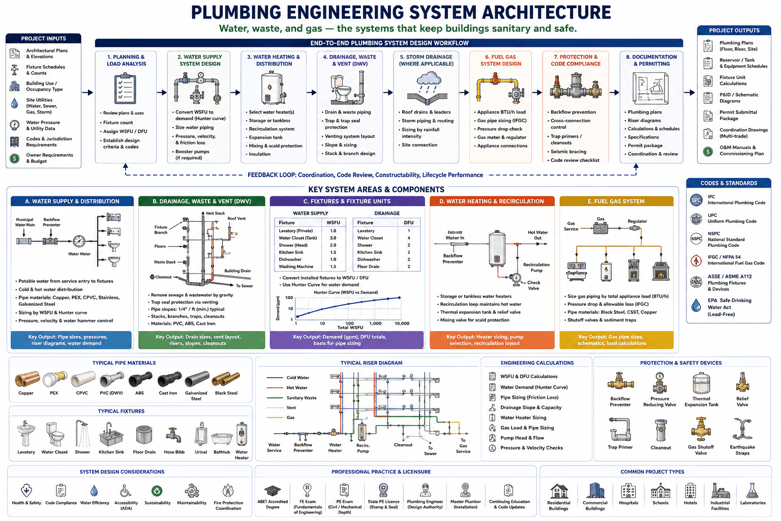
Hover, tap, or focus any component on the drawing (or a circuit below it) for details. Click to pin; move away or click again to clear.
Component Reference
Every component in the diagram above, grouped by section, with its role and the relevant standard.
Project Inputs
Architectural Plans & Elevations
Floor plans, elevations, and sections from the architect that establish room layout, ceiling/floor depths, and wall locations. The plumbing engineer routes risers, branch piping, and fixture rough-ins against this base sheet set.
Fixture Schedules & Counts
The owner/architect-supplied list of plumbing fixtures by type and location, used to assign Water Supply Fixture Units (WSFU) and Drainage Fixture Units (DFU) for sizing every downstream pipe.
📘 IPC Table 604.3 / 709.1Building Use / Occupancy Type
The occupancy classification (residential, office, assembly, healthcare, industrial, etc.) that sets minimum fixture counts, peak-demand patterns, and applicable code chapters for the plumbing design.
📘 IPC Chapter 4 (Fixtures, Fixture Counts)Site Utilities (Water, Sewer, Gas, Storm)
Locations, capacities, and invert elevations of the municipal water main, sanitary sewer, storm sewer, and gas main serving the site — the connection points the entire plumbing system designs back to.
Water Pressure & Utility Data
Municipal static/residual water pressure and available flow at the property line. Sets whether a booster pump is required and drives service-entrance pipe sizing using the Hunter Curve demand method.
📘 IPC Chapter 6 (Water Supply)Codes & Jurisdiction Requirements
The adopted plumbing, fuel gas, and fixture code editions (IPC, UPC, or NSPC) plus local amendments for the Authority Having Jurisdiction (AHJ) — the governing rule set for every downstream design decision.
Owner Requirements & Budget
Owner-driven design standards, sustainability/water-efficiency targets, redundancy expectations, and the project budget that shape fixture selection, pipe material choices, and system complexity.
Project Outputs
Plumbing Plans (Floor, Riser, Site)
The coordinated floor plans, riser diagrams, and site utility plans that show every pipe, fixture, and connection at the scale needed for construction and permitting.
Reservoir / Tank & Equipment Schedules
Schedules listing every storage/tankless water heater, booster pump, expansion tank, and storage reservoir with model, capacity, and performance data for procurement and installation.
Fixture Unit Calculations
The documented WSFU and DFU tabulations, per fixture and cumulative by branch/stack, that justify every water-supply and drainage pipe size shown on the drawings.
📘 IPC Table 604.3 / 709.1P&ID / Schematic Diagrams
Piping and instrumentation-style single-line schematics for water supply, DWV, and fuel gas systems that show flow direction, valves, and equipment without architectural scale clutter.
Permit Submittal Package
The formal drawing set, calculations, and code-compliance narrative submitted to the local plumbing/building official for plan review and permit issuance.
Coordination Drawings (Multi-trade)
Overlay drawings coordinating plumbing routing with structural, mechanical, electrical, and fire protection systems to resolve clashes before construction — often produced in BIM.
O&M Manuals & Commissioning Plan
Operation and maintenance manuals, equipment cut sheets, and the commissioning plan that verify the installed system performs as designed and hand off maintenance knowledge to the owner.
Codes & Standards
IPC — International Plumbing Code
The International Plumbing Code (ICC) governs water supply, sanitary drainage, venting, and fixture requirements in most U.S. jurisdictions. Referenced throughout this workflow for fixture units, pipe sizing, and slope.
📘 IPC (ICC)UPC — Uniform Plumbing Code
The Uniform Plumbing Code (IAPMO), the primary alternative to the IPC, adopted in California, Nevada, and other western states with its own fixture-unit tables and venting rules.
📘 UPC (IAPMO)NSPC — National Standard Plumbing Code
The National Standard Plumbing Code, published by the PHCC, adopted in select Mid-Atlantic and Northeastern jurisdictions as a third major plumbing code family alongside IPC and UPC.
📘 NSPCIFGC / NFPA 54 — International Fuel Gas Code
The International Fuel Gas Code (identical in substance to NFPA 54, the National Fuel Gas Code) governs gas piping sizing, materials, shutoffs, and appliance connections for natural gas and propane systems.
📘 IFGC / NFPA 54ASSE / ASME A112 — Plumbing Fixtures & Devices
ASSE and ASME A112 series product standards certify backflow preventers, relief valves, fixture fittings, and other plumbing devices for performance and safety — referenced whenever a device is specified.
📘 ASSE / ASME A112EPA Safe Drinking Water Act (Lead-Free)
Federal law requiring "lead-free" wetted surfaces (≤0.25% weighted average lead content) on pipes, fittings, and fixtures used in potable water systems — governs material selection for the water supply system.
📘 EPA SDWA (Lead-Free)Design Workflow
1. Planning & Load Analysis
Review architectural plans and building use, count fixtures, assign WSFU/DFU per fixture, and establish design criteria and the governing code edition. The foundation every later step sizes against.
📘 IPC Chapter 42. Water Supply System Design
Convert WSFU to a peak design demand using the Hunter Curve probability method, size cold and hot water piping for velocity and friction loss, and add booster pumps if street pressure is insufficient.
📘 IPC Chapter 6 (Water Supply)3. Water Heating & Distribution
Select storage or tankless water heater(s), design the hot-water recirculation system and expansion tank, and add mixing valves for scald protection and pipe insulation for efficiency.
📘 IPC Chapter 5 (Water Heaters)4. Drainage, Waste & Vent (DWV)
Design drain and waste piping with correct slope, protect trap seals with proper venting layout, and size stacks and branches for the DFU load calculated in Step 1.
📘 IPC Chapter 7 (Sanitary Drainage) / Chapter 9 (Vents)5. Storm Drainage (Where Applicable)
Size roof drains and leaders, route storm piping, and size the system for local rainfall intensity before connecting to the site storm sewer or detention system.
📘 IPC Chapter 11 (Storm Drainage)6. Fuel Gas System Design
Total the connected appliance BTU/h load, size gas piping to the IFGC pressure-drop limit, and place the gas meter, regulator, and appliance connections.
📘 IFGC / NFPA 547. Protection & Code Compliance
Add backflow prevention and cross-connection control, trap primers and cleanouts, seismic bracing where required, and run the full code-review checklist before documentation.
📘 ASSE / ASME A1128. Documentation & Permitting
Finalize plumbing plans, riser diagrams, calculations and schedules, and specifications, then assemble the permit package for coordination and AHJ review.
Feedback Loop: Coordination, Code Review, Constructability, Lifecycle Performance
A feedback path runs from Documentation & Permitting back to Planning & Load Analysis — code-review comments, multi-trade coordination clashes, constructability issues, and lifecycle performance data all loop back to revise earlier design decisions.
Water Supply & Distribution
Water Supply Service Diagram
The service entry sequence: municipal water main, backflow preventer at the service entrance, water meter, then branch piping distributing to fixtures. This is the physical layout Step 2 of the workflow sizes.
📘 IPC Chapter 6Water Supply & Distribution — Design Notes
Potable water is distributed from the service entry to fixtures as cold and hot water in Copper, PEX, CPVC, Stainless, or Galvanized Steel piping, sized by WSFU and the Hunter Curve, with pressure, velocity, and water-hammer control. Key output: pipe sizes, pressures, riser diagrams, and water demand.
📘 IPC Chapter 6 (Water Supply)Drainage, Waste & Vent (DWV)
DWV Riser Diagram
The drain-waste-vent stack schematic: fixture branches tie into the waste stack per floor, the vent stack rises to a roof vent to protect trap seals, and everything gravity-drains through the building drain to the sewer via a cleanout.
📘 IPC Chapter 7 / Chapter 9Drainage, Waste & Vent — Design Notes
Sewage and wastewater are removed by gravity; trap seals are protected via proper venting; pipe slopes are typically 1/4 in. per foot minimum; stacks, branches, traps, and cleanouts use PVC, ABS, or Cast Iron. Key output: drain sizes, vent layout, risers, slopes, and cleanouts.
📘 IPC Chapter 7 (Sanitary Drainage)Fixtures & Fixture Units
Water Supply Fixture Unit (WSFU) Table
The Water Supply Fixture Unit table (Lavatory 1.0, Water Closet-tank 3.0, Shower-head 2.0, Kitchen Sink 1.5, Dishwasher 1.0, Washing Machine 1.5) — sum per branch, then convert to design GPM via the Hunter Curve.
📘 IPC Table 604.3Drainage Fixture Unit (DFU) Table
The Drainage Fixture Unit table (Lavatory 1, Water Closet 4, Shower 2, Kitchen Sink 2, Dishwasher 2, Floor Drain 2) — sum per branch/stack to size drain, waste, and vent piping.
📘 IPC Table 709.1Fixture Unit Conversion & Hunter Curve
Installed fixtures convert to WSFU/DFU totals, then Hunter's Curve (probability-based demand vs. total WSFU) converts the fixture-unit sum into a peak design flow in GPM — the basis for every downstream pipe size. Key output: demand (GPM), DFU totals, basis for pipe sizing.
📘 IPC Chapter 6 (Hunter's Curve)Water Heating & Recirculation
Water Heater & Recirculation Diagram
Cold water enters through a backflow preventer to the water heater; hot water out feeds the building while a recirculation pump and check valve maintain a continuous hot-water loop back to the heater.
📘 IPC Chapter 5 (Water Heaters)Water Heating & Recirculation — Design Notes
Storage or tankless water heaters are selected per demand; a recirculation loop maintains hot water at fixtures; a thermal expansion tank and relief valve protect the closed system; a mixing valve provides scald protection. Key output: heater sizing, pump selection, recirculation layout.
📘 ASSE 1017 (Mixing Valves)Fuel Gas System
Fuel Gas Train Diagram
Gas service enters through the gas meter and regulator, then branches to each connected appliance — furnace/boiler, water heater, range/cooktop, and fireplace shown here as representative loads.
📘 IFGC / NFPA 54Fuel Gas System — Design Notes
Gas piping is sized by total appliance BTU/h load with an IFGC-limited pressure drop check; pipe materials are Black Steel, CSST, or Copper; shutoff valves and sediment traps are placed at each appliance. Key output: gas pipe sizes, schematics, load calculations.
📘 IFGC / NFPA 54Pipe Materials & Fixtures
Copper Pipe
Rigid copper tubing (Types K, L, M) is a long-standing standard for water supply and fuel gas — corrosion-resistant, solderable or press-fit, and rated for hot and cold potable water.
📘 ASTM B88PEX Pipe
Cross-linked polyethylene (PEX) is flexible, freeze-tolerant, and fast to install with crimp or expansion fittings — now the dominant material for residential and light-commercial water distribution.
📘 ASTM F876 / IPC Table 605.4CPVC Pipe
Chlorinated polyvinyl chloride (CPVC) is rated for both hot and cold potable water, solvent-welded, and a lower-cost rigid alternative to copper in many jurisdictions.
📘 ASTM D2846PVC (DWV) Pipe
Schedule 40 PVC is the standard drain-waste-vent (DWV) material for non-pressure sanitary drainage and venting — lightweight, solvent-welded, and code-accepted in most jurisdictions.
📘 ASTM D2665ABS Pipe
Acrylonitrile butadiene styrene (ABS) is an alternative DWV pipe material — solvent-welded like PVC but with better low-temperature impact resistance, common in colder regions.
📘 ASTM D2661Cast Iron Pipe
Cast iron soil pipe (hub-and-spigot or no-hub) offers superior sound dampening and fire resistance for DWV systems — common in high-rise and commercial construction where noise and fire rating matter.
📘 ASTM A888 / CISPI 301Galvanized Steel Pipe
Zinc-coated steel pipe used in older water distribution systems. Now largely superseded by copper, PEX, and CPVC because internal scale buildup reduces flow and accelerates corrosion over time.
📘 ASTM A53Black Steel Pipe
Threaded black steel pipe is the traditional standard for interior fuel gas piping — durable, code-accepted everywhere, and often paired with CSST for flexible branch runs.
📘 ASTM A53 / IFGCLavatory (Fixture)
The bathroom sink (lavatory) is the lightest-demand fixture on both the water-supply and drainage tables, typically 1.0 WSFU (private) and 1 DFU.
📘 IPC Table 604.3 / 709.1Water Closet (Fixture)
The water closet (toilet) is the highest-DFU common fixture at 4 DFU, and 3.0 WSFU for a tank-type unit — it usually governs branch and stack sizing on a floor.
📘 IPC Table 604.3 / 709.1Shower (Fixture)
A shower head fixture rated 2.0 WSFU and 2 DFU; multiple shower heads on one valve (as in gang showers) are counted individually for fixture-unit purposes.
📘 IPC Table 604.3 / 709.1Kitchen Sink (Fixture)
The kitchen sink, rated 1.5 WSFU and 2 DFU, is frequently paired with a garbage disposal and dishwasher branch and is a common grease-trap/interceptor source in commercial kitchens.
📘 IPC Table 604.3 / 709.1Floor Drain (Fixture)
Floor drains (2 DFU) are especially prone to trap-seal evaporation in low-use areas; primer devices or trap-seal protection are commonly required to keep sewer gas from entering the space.
📘 IPC Table 709.1Hose Bibb (Fixture)
An exterior hose bibb (sillcock) is a common cross-connection risk and typically requires an integral or add-on vacuum breaker for backflow protection.
📘 ASSE 1011 / 1052Urinal (Fixture)
Urinals are a lower-flush-volume alternative to water closets in commercial and institutional restrooms, contributing to fixture counts and water-efficiency calculations.
📘 IPC Chapter 4Bathtub (Fixture)
The bathtub is a standard residential fixture combining supply and drain demand similar to a shower, often sharing a trap with an adjacent shower in residential layouts.
📘 IPC Table 604.3 / 709.1Water Heater (Fixture Icon)
The water heater icon represents storage-tank or tankless equipment supplying the hot-water distribution and recirculation system detailed in Key System Area D.
📘 IPC Chapter 5Reference & Calculations
Typical Riser Diagram
A representative multi-floor riser showing Cold Water, Hot Water, Sanitary Waste, Vent, and Gas piping in their conventional line colors, from water service and backflow preventer, through the water heater and recirculation pump, to cleanouts, the sewer connection, and gas service. See the connection legend below the diagram for each line type.
Engineering Calculations
The core plumbing engineering calculations: WSFU & DFU tabulation, water demand via Hunter Curve, pipe sizing by friction loss, drainage slope & capacity, water heater sizing, gas load & pipe sizing, pump head & flow, and pressure & velocity checks.
📘 IPC / IFGCProtection & Safety Devices
Backflow Preventer
A backflow preventer (RPZ, DCVA, PVB, or AVB depending on hazard degree) stops contaminated water from siphoning or being pushed back into the potable water main at cross-connections.
📘 ASSE 1013 / 1015 / 1020Pressure Reducing Valve (PRV)
A pressure-reducing valve steps down high municipal static pressure to a safe working pressure at the building, protecting fixtures, appliances, and piping from damage and water hammer.
📘 ASSE 1003 / IPC 604.8Thermal Expansion Tank
A thermal expansion tank absorbs the volume increase as water heats in a closed system (one with a check valve or PRV), preventing dangerous pressure spikes at the water heater relief valve.
📘 ASSE 1017 / IPC 607Relief Valve
A temperature-and-pressure (T&P) relief valve automatically discharges water heater pressure or temperature that exceeds a safe threshold, preventing tank rupture.
📘 ASME/ANSI Z21.22Trap Primer
A trap primer periodically adds a small charge of water to an infrequently used floor-drain trap, preventing the trap seal from evaporating and letting sewer gas into the building.
📘 IPC 1002.4Cleanout
Cleanouts provide accessible entry points into drain, waste, and vent piping for rodding out blockages, required at specific intervals and direction changes along the DWV system.
📘 IPC 708Gas Shutoff Valve
A manual shutoff valve installed ahead of each gas appliance and at the building entrance, allowing isolation for service, emergency, or seismic shutoff.
📘 IFGC 409Earthquake Straps
Seismic straps anchor water heaters (and other tall equipment) to structural framing to prevent tipping and gas-line rupture during an earthquake — required in many seismic zones.
📘 IPC 508.2 (Seismic Bracing)Professional Practice & Project Types
System Design Considerations
Cross-cutting design drivers that shape every plumbing decision: health & safety, code compliance, water efficiency, accessibility (ADA), sustainability, maintainability, and fire protection coordination with the fire suppression trade.
Professional Practice & Licensure
The professional path underlying plumbing engineering: an ABET-accredited degree, the FE exam (Fundamentals of Engineering), the PE exam (Civil/Mechanical depth), a State PE License (stamp & seal) for design authority, versus the separate Master Plumber trade license for installation, plus ongoing continuing education and code updates.
📘 NCEES FE/PECommon Project Types
This end-to-end design workflow applies across residential buildings, commercial buildings, hospitals, schools, hotels, industrial facilities, and laboratories — each with its own fixture mix, code chapter emphasis, and reliability expectations.
Connections & Flows
The piping line types that tie the riser diagram together — each shown as a colored line in the legend above.
Cold Water
Potable cold water supply piping from the service entrance and backflow preventer to fixtures and the water heater inlet.
📘 IPC Chapter 6Hot Water
Hot water distribution and recirculation piping from the water heater outlet to fixtures, sized separately from cold water for temperature and scald-protection requirements.
📘 IPC Chapter 5 / 607Sanitary Waste
Gravity drainage piping carrying sewage and wastewater from fixtures to the building drain and sewer connection, sized by DFU and sloped per code minimums.
📘 IPC Chapter 7Vent
Vent piping that admits air to the drainage system to protect trap seals and equalize pressure, terminating through the roof.
📘 IPC Chapter 9Gas
Fuel gas piping from the gas service and meter/regulator to connected appliances, sized by total BTU/h load and allowable pressure drop.
📘 IFGC / NFPA 54